STANDARD OPERATING PROCEDURES
- GENERAL INFORMATION
FOREWORD
The procedures contained in this Chapter are recommended by Airbus, and are consistent with the
other Chapters of this manual.
The Authorities do not certificate Standard Operating Procedures.
The manufacturer presents them herein as the best way to proceed,
from a technical and operational standpoint.
They are continually updated and the revisions take into account Operator input,
as well as manufacturer experience.
In addition, Operators may amend them, as needed.
However, the manufacturer recommends that Operators using the FCOM as onboard
operational manual submit suggested changes to expedite
publication, and maintain consistency of the manual.
The Operator should note that they may rewrite this Chapter, at their own responsibility;
this could, however, make it difficult to update the manual
and keep it consistent with the other Chapters.
The following sections contain expanded information on normal procedures.
Standard Operating Procedures consist of inspections, preparations, and normal procedures.
All items of a given procedure are listed in a sequence that follows
a standardized scan of the cockpit panels, unless that sequence goes against
the action priority logic, to ensure that all actions are
performed in the most efficient way.
Standard Operating Procedures are divided into flight phases, and are performed by memory.
These procedures assume that all systems are operating normally, and that all automatic functions
are used normally.
Some normal procedures, that are non-routine will be found in the SUPPLEMENTARY
TECHNIQUES (Refer to PRO-SUP-10 General), and in the SPECIAL OPERATIONS (Refer to
PRO-SPO-20 General).
______________________________________________________________________________________________
FLIGHT PREPARATION
TECHNICAL CONDITION OF THE AIRCRAFT
The crew will verify the technical state of the aircraft (deferred defect list), with regard to
airworthiness, acceptability of malfunctions (MEL), and influence on the flight plan.
WEATHER BRIEFING
‐ The crew will get a weather briefing
‐ The briefing should include:
• Actual and expected weather conditions, including runway conditions for takeoff and climb-out
• Significant weather enroute, including winds and temperatures
• Terminal forecasts for destination and alternate airports
• Actual weather for destination and alternates,
for short range flights and recent past weather, if available
• Survey of the meteorological conditions at airports along the planned route.
Weather can affect the choice of routing (for example, influence which route is quickest) and
the choice of flight level.
The pilot must also consider the possibility of runways being contaminated
at the departure and destination airfields.
The pilot must also verify ISA deviations and enroute icing conditions,
and must consider the possibility of holding due to weather at the destination.
NOTAMS
to: PR-AVB, PR-AVC, PR-AVD
‐ The flight crew must examine NOTAMs for changes to routings, unserviceable navaids, availability
of runways and approach aids etc, all of which may affect the final fuel requirement
‐ In order to prevent the risks of projection of debris towards the trimmable horizontal stabilizer
and the elevators, it is not recommended to takeoff from runways in bad condition (loose surface,
under repair, covered with debris...).
NOTAMS
to: PR-AVH, PR-AVJ, PR-AVK, PR-AVL, PR-AVO, PR-AVP, PR-AVQ, PR-AVR
‐ The flight crew must examine NOTAMs for changes to routings, unserviceable navaids, availability
of runways and approach aids etc, all of which may affect the final fuel requirement
‐ In order to prevent the risks of projection of debris towards the trimmable horizontal stabilizer
and the elevators, it is not recommended to takeoff from runways in bad condition (loose surface,
under repair, covered with debris...)
‐ GPS Primary availability:
• For RNP AR operations, the GPS Primary availability prediction should be checked to ensure
the RNP will be available for the estimated time of operation.
FLIGHT PLAN AND OPERATIONAL REQUIREMENTS
Applicable to: ALL
‐ The pilot will check the company flight plan for routing, altitudes, and flight time
‐ The Captain will check the ATC flight plan and ensure that:
• It is filled in and filed, in accordance with the prescribed procedures
• It agrees with the fuel flight plan routing.
‐ The crew will check the estimated load figures, and will calculate the maximum allowable takeoff
and landing weights.
OPTIMUM FLIGHT LEVEL
Applicable to: ALL
The flight crew should choose a flight level that is as close to the optimum as possible.
To obtain the optimum flight level, use the chart in the QRH or in the FCOM
(Refer to PER-FPL-FLP-ALT-10 DEFINITIONS).
As a general rule, an altitude that is 4 000 ft below the optimum produces a significant penalty
(approximately 5 % of fuel).
Flight 8 000 ft below the optimum altitude produces a penalty of more
than 10 % against trip fuel.
(The usual contingency allowance is 5 %).
FUEL REQUIREMENTS
Applicable to: ALL
COMPUTERIZED FLIGHT PLAN CHECK
In most cases the flight crew uses a computer-derived flight plan to obtain the correct fuel
requirements. Although these computerized requirements are normally accurate, the flight crew
must check them for gross errors.
The easiest way to do this is to use the “Quick Determination of F-PLN” tables
(Refer to PER-FPL-FLP-QFP-40 FLIGHT PLANNING M.78).
Although the aircraft will fly at ECON MACH
that is based on the cost index, the M 0.78 table is accurate enough to permit the crew to check for
gross error.
Ensure that both the captain and the first officer have verified that the fuel calculations and
required fuel on board are correct and that the figure complies with the applicable regulations.
FUEL TRANSPORTATION
The flight crew must check the policy covering the “tankering” of fuel on sectors where there is a
favourable fuel price differential or operational requirement.
Remember that carrying unnecessary extra fuel increases the fuel consumption for that sector and
therefore reduces the economy of the operation (lower flex temperature, more tire and brake wear,
more time in climb phase, lower optimum flight level etc).
________________________________________________________________________________________________
- SAFETY EXTERIOR INSPECTION
Applicable to: ALL
Items marked by (*) are the only steps to be completed during a transit stop.
This inspection ensures that the aircraft and its surroundings are safe for operations.
On arriving at the aircraft, check for obstructions in the vicinity, engineering activity, refueling, etc.
* WHEEL CHOCKS................................................. CHECK IN PLACE
* LANDING GEAR DOORS............................................CHECK POSITION
WARNING
Do not pressurize the green hydraulic system without clearance from ground
personnel, if any gear door is open. Remember that the green hydraulic system is
pressurized if the yellow system is pressurized and the PTU is on AUTO.
* APU AREA...............................................................CHECK
Observe that the APU inlet and outlet are clear.
_________________________________________________________________________________________________
- PRELIMINARY COCKPIT PREPARATION
Items marked by asterisks (*) are the only steps to be completed during a transit stop.
The following procedure, performed by the PNF, ensures that all the required checks are performed
before applying electrical power to avoid inadvertent operation of systems and danger to the aircraft
and personnel.
Included is APU starting and the establishment of electrical and pneumatic power.
AIRCRAFT POWER UP
ENG MASTER 1 sw and MASTER 2 sw........................................OFF
MODE selector.........................................................NORM
L/G lever..............................................CHECK DOWN position
CAPT WIPER selector and F/O WIPER selector.............................OFF
If the aircraft has not been electrically supplied for 6 h or more,
perform the followingcheck:
BAT 1 pb and BAT 2 pb............................................ CHECK OFF
BAT 1 and 2 VOLTAGE......................................CHECK ABOVE 25.5 V
Battery voltage above 25.5 V ensures a charge above 50 %.
If battery voltage is below 25.5 V:
A charging cycle of about 20 min is required.
BAT 1 pb and BAT 2 pb..................................................AUTO
EXT PWR pb...............................................................ON
Check on ELEC SD page, that the battery contactor is closed and the b
atteries are charging.
After 20 min:
BAT 1 + 2 pb............................................................OFF
BAT 1 and 2 VOLTAGE......................................CHECK ABOVE 25.5 V
If battery voltage is above 25.5 V:
BAT 1 pb and BAT 2 pb..................................................AUTO
If the APU is started on batteries only, it should be started within 30 min
after the selection of batteries to AUTO
(35 min after battery selection to AUTO, the battery charge is less
than 25 % of maximum capacity).
If the aircraft has been electrically supplied during the last 6 h:
BAT 1 pb and BAT 2 pb...................................................AUTO
EXT PWR pb (when AVAIL light is on)...................................... ON
AVAIL light goes out.
WARNING Do not pressurize hydraulic systems without clearance from ground crew.
APU FIRE TEST/START
APU FIRE pb-sw................................................IN and GUARDED
AGENT lights ........................................................... OUT
If the APU is already running, ensure that the following check has
already been completed. If not, perform it.
APU FIRE TEST pb.......................................................PRESS
Check :
‐ APU FIRE warning on ECAM + CRC + MASTER WARN light (if AC Power available).
‐ APU FIRE pb-sw lighted red.
‐ SQUIB light and DISCH light on
APU START
If the EXT PWR pb ON light is on:
APU MASTER SW pb-sw......................................................ON
ON light comes on.
APU SD page appears on ECAM.
APU START pb-sw......................................................... ON
Note: Wait at least 5 s before selecting APU START pb-sw.
The FLAP OPEN indication appears on APU SD page.
On the APU SD page, N and EGT rise.
When N = 95 %:
‐ On APU SD page, AVAIL indication appears.
‐ On APU panel : START ON light goes out.
AVAIL light comes on.
10 s later:
‐ DOOR SD page replaces APU SD page.
EXT PWR pb.......................................................... AS RQRD
External power may be kept ON to reduce the APU load, especially in hot conditions:
When APU BLEED pb-sw is ON, keeping the EXT PWR pb ON enables to increase the bleed air
flow of the APU, thus improving the efficiency of the air conditioning.
If the EXT PWR pb ON light is off:
APU MASTER SW pb-sw.......................................................ON
ON light comes on.
APU START pb-sw.......................................................... ON
Note: Wait at least 5 s before selecting APU START pb-sw.
At 95 % RPM:
‐ START ON light goes out.
‐ AVAIL light comes on.
‐ APU GEN comes on line.
‐ APU SD page appears after 10 s.
If required, adjust brightness on ECAM control panel.
10 s later:
‐ DOOR SD page replaces APU SD page.
_______________________________________________________________________________________________________
BEFORE WALK-AROUND
* COCKPIT LIGHTS...................................................AS RQRD
‐ Set OVHD INTEG LT knob, STBY COMPASS sw, DOME sw, ANN LT sw as required.
‐ Set FLOOD LT, and INTEG LT as required.
DOME light should be on because it is the only lighting source in the
EMER ELEC configuration. The DIM position is recommended for takeoff.
FLAPS........................................................CHECK POSITION
Check the upper ECAM display to confirm that the FLAPS position
agrees with the handle position.
* SPEEDBRAKE lever............................. CHECK RETRACTED and DISARMED
WARNING If flight control surface positions do not agree with
the control handle positions, check with the maintenance
crew before applying hydraulic power.
* PRK BRK handle.........................................................ON
* ACCU PRESS indicator & BRAKES PRESS indicator...................... CHECK
‐ Check for normal indications.
‐ The ACCU PRESS indication must be in the green band.
If required use the electric pump on yellow hydraulic system
to recharge the brake accumulator.
WARNING Yellow and green hydraulic systems are pressurized
from yellow electric pump.
Get ground crew clearance before using the electric pump.
PROBE/WINDOW HEAT pb........................................... CHECK AUTO
APU BLEED pb-sw...........................................................ON
Do not use APU BLEED, if ground personnel confirms that ground air unit is connected.
Pilots should also check the BLEED SD page to determine whether an HP ground air unit
is connected (pressure in the bleed system).
ALL WHITE LIGHTS..........................................................OFF
X BLEED selector.........................................................AUTO
Zone temperature selectors........................................... AS RQRD
Full range temperature 24 ± 6 °C (75 ± 11 °F).
CARGO HEAT SELECTORS..................................................AS RQRD
Set temperature selectors, as required.
ELEC.......Scan/check that there are no amber lights, except GEN FAULT lights.
VENT.....................................................Check all lights off.
Applicable to: PR-AVB, PR-AVC, PR-AVD, PR-AVP, PR-AVQ, PR-AVR
* ECAM
* RCL key ...............................................................PRESS
‐ Press the RCL key for 3 s to recall all warnings that have been CLR or CNL
‐ If applicable, check warnings compatible with MEL, then CLEAR or CANCEL them.
If any action is required, call maintenance personnel as soon as possible.
* DOOR key...............................................................PRESS
If the oxygen pressure is half boxed in amber, check “MIN FLT CREW OXY CHART”
to verify if the pressure is sufficient for the scheduled flight
(Refer to LIM-35 Cockpit Fixed Oxygen System).
_______________________________________________________________________________
319/320

(1) REF TEMPERATURE :
‐ On ground : REF TEMPERATURE = (OAT + COCKPIT TEMP) / 2
‐ In flight : REF TEMPERATURE (deg. C) = CAB TEMP (deg. C) -10 °C
or
REF TEMPERATURE (deg. F) = CAB TEMP(deg.F)-18 °F
(2) MINIMUM BOTTLE PRESSURE TO TAKE INTO ACCOUNT :
‐ Preflight checks
‐ The use of oxygen, when only one flight crewmember is in the cockpit
‐ Unusable quantity (to ensure that the regulator functions with minimum pressure)
‐ Normal system leakage
‐ and
Protection after loss of cabin pressure, with mask regulator on NORMAL (diluted oxygen):
‐ During an emergency descent : For all cockpit members for 22 min
‐ During cruise at FL 100 : For 2 flight crewmembers for 98 min.
or
Protection in case of smoke, with 100 % oxygen :
For all cockpit members for 15 min at a cabin altitude of 8 000 ft.
Note: The above times are based on the use of a sealed mask, but may be shorter (in terms of performance,
pressure or duration) if the flight crewmember has a beard.
___________________________________________________________________________________
* HYD key................................................................PRESS
Check that the quantity indexes are in the normal filling range.
* ENG key.................................................................PRESS
Check that the oil quantity is at or above 9.5 qts + estimated consumption
(maximum average estimated consumption ∼ 0.5 qt/h).
Applicable to: PR-AVH, PR-AVJ, PR-AVK, PR-AVL, PR-AVO
* ECAM
* RCL key ................................................................PRESS
‐ Press the RCL key for 3 s to recall all warnings that have been CLR or CNL
‐ If applicable, check warnings compatible with MEL, then CLEAR or CANCEL them.
If any action is required, call maintenance personnel as soon as possible.
* DOOR key.................................................................PRESS
If the oxygen pressure is half boxed in amber, check “MIN FLT CREW OXY CHART”
to verify if the pressure is sufficient for the scheduled flight
(Refer to LIM-35 Cockpit Fixed Oxygen System).
________________________________________________________________________________
318
_

(1) REF TEMPERATURE :
‐ On ground : REF TEMPERATURE = (OAT + COCKPIT TEMP) / 2
‐ In flight : REF TEMPERATURE (deg. C) = CAB TEMP (deg. C) -10 °C
or
REF TEMPERATURE (deg. F) = CAB TEMP(deg.F)-18 °F
(2) MINIMUM BOTTLE PRESSURE TO TAKE INTO ACCOUNT :
‐ Preflight checks
‐ The use of oxygen, when only one flight crewmember is in the cockpit
‐ Unusable quantity (to ensure that the regulator functions with minimum pressure)
‐ Normal system leakage
‐ and
Protection after loss of cabin pressure, with mask regulator on NORMAL (diluted oxygen):
‐ During an emergency descent : For all cockpit members for 22 min
‐ During cruise at FL 100 : For 2 flight crewmembers for 98 min.
or
Protection in case of smoke, with 100 % oxygen : For all cockpit members
for 15 min at a cabin altitude of 8 000 ft.
Note: The above times are based on the use of a sealed mask, but may be shorter
(in terms of performance, pressure or duration) if the flight crewmember has a beard.
________________________________________________________________________________
* HYD key..................................................................PRESS
Check that the quantity indexes are in the normal filling range.
* ENG key..................................................................PRESS
‐ If indications are not available, set the FADEC GND PWR pb on
the overhead panel to ON, to supply the FADEC.
Check that the oil quantity is at or above 8.7 qt + estimated consumption
(maximum average estimated consumption ∼ 0.4 qt/h).
Applicable to: ALL
* OPERATIONS ENGINEERING BULLETINS (OEB)
* OEB in QRH................................................................CHECK
Go to the OEB section of the QRH and review all OEBs (particularly red OEBs) that are applicable
to the aircraft.
Note: If there is a transfer of duties during this flight, the flight crew must remind the incoming
flight crew of the applicable OEB(s) during the briefing that is done when transferring the
duties.
EMERGENCY EQUIPMENT
Check the following equipment:
‐ Life jackets stowed
‐ Axe stowed
‐ Smoke hoods or portable oxygen equipment and full face masks stowed and serviceable
‐ Portable fire extinguisher lockwired and pressure in the green area
‐ Smoke goggles stowed (smoke hoods )
‐ Oxygen masks stowed
‐ Flashlights stowed
‐ Escape ropes stowed
RAIN REPELLENT
Pressure and quantity indicators......................................CHECK
CAUTION Never use rain repellent to wash the windshield and never use
it on a dry windshield.
REAR and OVERHEAD CIRCUIT BREAKERS panels............................ CHECK
Check that all circuit breakers are set. Reset as necessary.
* GEARS PINS and COVERS...............................................CHECK
Check that three are on board and stowed.
_________________________________________________________________________________________
- EXTERIOR INSPECTION
GENERAL
The exterior inspection ensures that the overall condition of the aircraft and its visible components
and equipment are safe for the flight.
Complete inspection is normally performed by maintenance personnel or in the absence of
maintenance personnel by a flight crew member before each originating flight.
Items marked by asteriks (*) must be performed again by a flight crew member before each flight.
The parking brake must be ON during the exterior inspection to allow the flight crew to check brake
wear indicators.
‐ Check structure for impact damage
‐ Check that there is no evident fuel, oil or hydraulic leaks.
WARNING If a landing gear door is open, contact the maintenance crew before applying
hydraulic power.
EXTERIOR WALK-AROUND

LH FWD FUSELAGE
* AOA probes.................................................... CONDITION
F/O and CAPT static ports......................................... CLEAR
Avionics equipment vent air inlet valve....................... CONDITION
Oxygen bay....................................................... CLOSED
Oxygen overboard discharge indicator.............................. GREEN
* Toilet servicing door ........................................... CLOSED
NOSE SECTION
* Pitot probes...................................................CONDITION
STBY static ports..................................................CLEAR
* TAT probes.................................................... CONDITION
* Radome and latches.................................... CONDITION/LATCHED
Forward avionics compartment door.................................CLOSED
Ground electrical power door (if not required.)...................CLOSED
NOSE L/G
* Nose wheel chocks.............................................. IN PLACE
* Wheels and tires...............................................CONDITION
Nose gear structure........................................... CONDITION
Taxi, TO, turn-off lights......................................CONDITION
Hydraulic lines and electrical wires.......................... CONDITION
Wheel well........................................................ CHECK
Safety pin.......................................................REMOVED
RH FWD FUSELAGE
RH + AFT avionic compartment doors............................... CLOSED
Avionic equipment vent air outlet valve........................CONDITION
F/O-CAPT static ports..............................................CLEAR
* AOA probe..................................................... CONDITION
Forward cargo door and selector panel..............................CHECK
LOWER CENTER FUSELAGE
Potable water drain panel ....................................... CLOSED
Antennas........................................................ CONDITION
Drain mast.......................................................CONDITION
RAM air inlet flap...............................................CONDITION
LP and HP ground connection doors.................................. CLOSED
Anticollision light..................................................CHECK
CTR TK magnetic fuel level...........................................FLUSH
Pack air intakes and outlets........................................ CLEAR
Applicable to: ALL
RH CENTER WING
Yellow hydraulic bay door.........................................CLOSED
Fuel panel........................................................CLOSED
Inner tank magnetic fuel.......................................... FLUSH
Landing light..................................................CONDITION
* Slat 1.........................................................CONDITION
ENG 2 LH SIDE
Oil fill access door (CFM and IAE only)............................ CLOSED
Master magnetic chip detector access door (IAE only)............... CLOSED
* Thrust Recovery Nozzle (PW only)..........................CLOSED/LATCHED
Hydraulic filter visual access door (PW only).................... CLOSED
* Fan cowl doors............................................CLOSED/LATCHED
* Drain mast.............................................CONDITION/NO LEAK
* Engine inlet and fan blades....................................... CHECK
ENG 2 RH SIDE
Vent inlet (CFM only)................................................CLEAR
Pressure-relief/Start valve handle access door (CFM and IAE only)...CLOSED
Nose cowl pressure relief door (PW only)............................CLOSED
Eng oil fill access/starter air vlv override access door (PW).......CLOSED
Master chip detector access door (PW only)..........................CLOSED
IDG servicing access door (PW only).................................CLOSED
Turbine exhaust .....................................................CLEAR
Pylon/access panel....................................... CONDITION/CLOSED
to: PR-AVP, PR-AVQ, PR-AVR
RH WING LEADING EDGE
* Slats 2, 3, 4, 5...............................................CONDITION
Magnetic fuel level............................................... FLUSH
Fuel water drain valve.......................................... NO LEAK
Refuel coupling...................................................CLOSED
Surge tank air inlet.............................................. CLEAR
* Fuel ventilation overpressure disc............................... INTACT
Navigation.................................................... CONDITION
* Wing tip.......................................................CONDITION
RH WING TRAILING EDGE
Static dischargers.................................................CHECK
* Control surfaces...............................................CONDITION
* Flaps and fairings............................................ CONDITION
RH L/G AND FUSELAGE
* Chocks.......................................................... REMOVED
* Wheels and tires...............................................CONDITION
Brakes and brake wear ind..................................... CONDITION
Torque link damper ............................................CONDITION
Hydraulic lines................................................... CHECK
Landing gear structure............................................ CHECK
Downlock springs...................................................CHECK
Safety pin.......................................................REMOVED
Ground hydraulic connection yello................................ CLOSED
Water drain mast ........................................... CONDITION
Shroud fuel drain......................................CONDITION/NO LEAK
RH AFT FUSELAGE
Cargo door and selector panel..................................... CHECK
Bulk door ...................................................... CHECK
* Toilet service access door....................................... CLOSED
Outflow valve................................................. CONDITION
Drain mast ................................................... CONDITION
Flight recorder access door ......................................CLOSED
TAIL
* Stabilizer, elevator, fin, and rudder..........................CONDITION
Static dischargers.................................................CHECK
* Lower fuselage structure (tail impact on runway)...............CONDITION
APU
Access doors........................................................CLOSED
Air intake.......................................................CONDITION
Drain....................................................CONDITION/NO LEAK
Oil cooler air outlet .............................................. CLEAR
Exhaust..............................................................CLEAR
Navigation light................................................ CONDITION
Fire extinguisher overpressure indication (red disc)............. IN PLACE
LH AFT FUSELAGE
* Stabilizer, elevator, fin, and rudder..........................CONDITION
* Potable water service door....................................... CLOSED
Ground hydraulic connection blue door.............................CLOSED
Ground hydraulic connection green and reservoir filling door......CLOSED
LH LANDING GEAR
* Chocks........................................................... REMOVED
* Wheels and tires................................................CONDITION
Brakes and brake wear indicator.................................CONDITION
Torque link damper .............................................CONDITION
Hydraulic lines.................................................... CHECK
Landing gear structure............................................. CHECK
Downlock springs................................................... CHECK
Safety pin........................................................REMOVED
LH WING TRAILING EDGE
* Flaps and fairing.............................................. CONDITION
* Control surfaces................................................CONDITION
Static dischargers..................................................CHECK
LH WING LEADING EDGE
* Wing tip........................................................CONDITION
Navigation light............................................... CONDITION
Surge tank air inlet............................................... CLEAR
* Fuel ventilation overpressure disc................................ INTACT
Fuel water drain valve........................................... NO LEAK
Inner and outer cell magnetic fuel level............................FLUSH
* Slats 2, 3, 4, 5................................................CONDITION
to: PR-AVB, PR-AVC, PR-AVD, PR-AVP, PR-AVQ, PR-AVR
ENG 1 LH SIDE
Oil fill access door...............................................CLOSED
* Fan cowl doors.............................................CLOSED/LATCHED
* Drain mast..............................................CONDITION/NO LEAK
* Engine inlet and fan blades.........................................CHECK
Applicable to: PR-AVH, PR-AVJ, PR-AVK, PR-AVL, PR-AVO
ENG 1 LH SIDE
* Thrust Recovery Nozzle.................................... CLOSED/LATCHED
Hydraulic filter visual door.......................................CLOSED
* Fan cowl doors.............................................CLOSED/LATCHED
* Drain mast..............................................CONDITION/NO LEAK
* Engine inlet and fan blades........................................ CHECK
to: PR-AVB, PR-AVC, PR-AVD, PR-AVP, PR-AVQ, PR-AVR
ENG 1 RH SIDE
Vent inlet........................................................... CLEAR
Pressure relief/Start valve handle access door...................... CLOSED
Turbine exhaust...................................................... CLEAR
Pylon/access panel........................................ CONDITION/CLOSED
to: PR-AVH, PR-AVJ, PR-AVK, PR-AVL, PR-AVO
ENG 1 RH SIDE
Nose cowl pressure relief door........................................CLOSED
Engine oil fill access/starter air valve override access door.........CLOSED
Master chip detector access door......................................CLOSED
IDG servicing access door.............................................CLOSED
Turbine exhaust....................................................... CLEAR
Pylon/access panel......................................... CONDITION/CLOSED
LH CENTER WING
* Slat 1...........................................................CONDITION
Wing leading edge ventilation intake ............................... CLEAR
Fuel water drain valves............................................NO LEAK
Inner tank magnetic fuel............................................ FLUSH
Landing lights...................................................CONDITION
Hydraulic reservoir pressurization door............................ CLOSED
RAT doors.......................................................... CLOSED
___________________________________________________________________________________________________
- COCKPIT PREPARATION
INTRODUCTION
Items marked by (*) are the only steps to be completed during a transit stop.
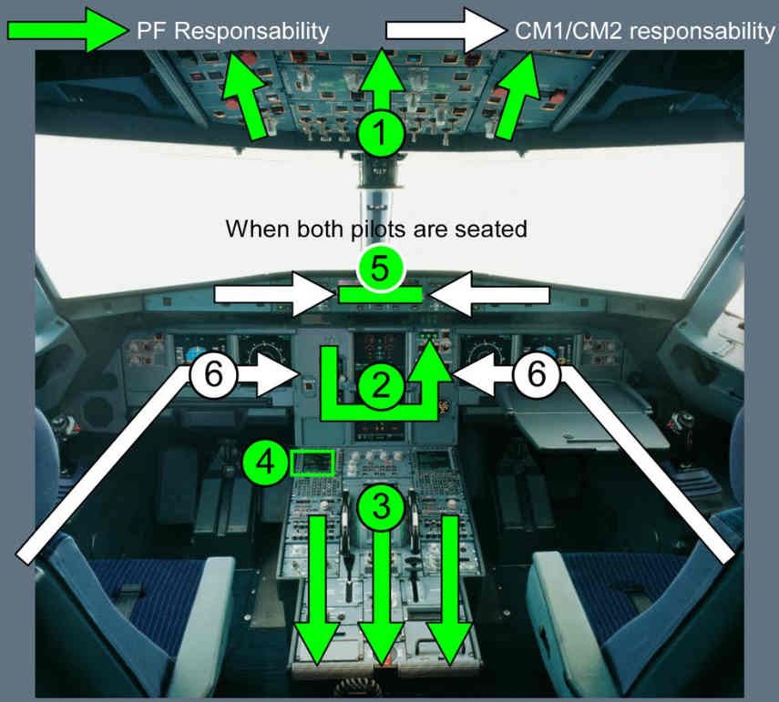
The PF and PNF should perform the cockpit preparation according to the panel scan sequence
defined below (Refer to Panel Scan Sequence), and the task sharing defined in the QRH
(Refer to QRH/Task Sharing for Abnormal/Emergency Procedures).
DOCUMENTATION AND MAINTENANCE
On entering the aircraft, obtain the technical (maintenance) log and verify that the certificate of
maintenance and daily inspection (or similar) are up to date and signed. Check the deferred or
carried-forward defects. If refueling has already been completed, check the uplift.
PANEL SCAN SEQUENCE

Nenhum comentário:
Postar um comentário