PURPOSE OF THE ECAM
The Electronic Centralized Aircraft Monitoring (ECAM) system
is a main component of Airbus’ two-crewmember cockpit,
which also takes the "dark cockpit" and "forward-facing crew"
philosophiesinto account.
The purpose of the ECAM is to:
• Display aircraft system information
• Monitor aircraft systems
• Indicate required flight crew actions, in most normal, abnormal and emergency situations.
As the ECAM is available in most failure situations,
it is a significant step in the direction towards a
paperless cockpit and the reduction of memory items.
MAIN PRINCIPLES
Applicable to: ALL
INFORMATION PROVIDED WHEN NEEDED
One of the main advantages of the ECAM is that it displays applicable information to the flight
crew, on an "as needed" basis.
The following outlines the ECAM’s operating modes:
• Normal Mode:
Automatically displays systems and memos, in accordance with the flight phase.
• Failure Mode:
Automatically displays the appropriate emergency/abnormal procedures, in addition to their
associated system synoptic.
• Advisory Mode:
Automatically displays the appropriate system synoptic, associated with a drifting parameter.
• Manual Mode:
Enables the flight crew to manually select any system synoptic
via the ECAM Control Panel(ECP).
Most warnings and cautions are inhibited during critical phases of flight
(T/O INHIBIT – LDGINHIBIT), because most system failures will not affect
the aircraft’s ability to continue a takeoff or landing.
FAILURE LEVELS
The ECAM has three levels of warnings and cautions. Each level is based on the associated
operational consequence(s) of the failure. Failures will appear in a specific color,
according to a defined color-coding system,
that advises the flight crew of the urgency of a situation in an
instinctive, unambiguous manner.
In addition, Level 2 and 3 failures are accompanied by a specific
aural warning: A Continuous Repetitive Chime (CRC) indicates a Level 3 failure, and a Single
Chime (SC) indicates a Level 2 failure.
LVL 3 Priority: Safety ||Color Code: Red ||Aural Warning: CRC ||
Crew Act: Immediate
LVL 2 Priority: Abnormal ||Color Code: Amber ||Aural Warning: SC ||
Crew Act: Awareness, then action
LVL 1 Priority: Degradation||Color Code: Amber ||Aural Warning: None ||
Crew Act: Awareness, then Monitor
When there are several failures, the FWC displays them on the Engine Warning Display (E/WD) in
an order of priority, determined by the severity of the operational consequences.
This ensures that the flight crew sees the most important failures first.
FEEDBACK
The ECAM provides the flight crew with feedback, after action is taken on affected controls:
• The System Synoptic:
Displays the status change of affected components.
• The Memo:
Displays the status of a number of systems selected by the flight crew (e.g. anti ice).
• The Procedures:
When the flight crew performs a required action on the cockpit panel, the ECAM usually clears
the applicable line of the checklist (except for some systems or actions, for which feedback is
not available).
The ECAM reacts to both failures and pilot action.
ECAM HANDLING
Applicable to: ALL
Task sharing is essential to effective ECAM operation, particularly in the case of abnormal
operations.
NORMAL OPERATIONS
On ground, the ECAM MEMO is reviewed for feedback on temporarily-selected items
(e.g. SEATBELTS/IGNITION/ENG A/I), and to check whether IRs are aligned.
If alignment is not complete,the time remaining will be displayed.
It is, therefore, not necessary to refer to the OVHD panel.
In cruise, the main systems should periodically be reviewed during flight
(ENG, BLEED, ELEC, AC/DC, HYD, FUEL, F/CTL),
to ensure that they are operating normally, and to detect any
potential problem in advance.
The ECAM MEMO must be included in the instrument review.
In cruise, in most of the cases, it should be blank.
It helps to make the flight crew aware of any system that a flight crewmember
temporarily selected, but forgot to deselect.
A STS label, displayed at the bottom of the E/WD, indicates that there is a STATUS to be
reviewed.
Therefore, when a C/L calls for STATUS review, press STS, only if the label appears.
If there is a STS at engine shutdown, it will pulse at the bottom of the E/WD.
If this is the case, the STATUS page should be reviewed for help in completing the technical log.
ECAM ADVISORY
The flight crewmember that first notices an advisory announces: "ADVISORY on XYZ system".
Then, the PF requests the PNF to review the drifting parameter.
If time permits, the PNF may refer to the QRH non normal procedures section,
containing recommended actions in various advisory situations.
1 ABNORMAL OPERATIONS
TASK SHARING RULES
When the ECAM displays a warning or a caution, the first priority is to ensure that a safe flight
path is maintained.
The successful outcome of any ECAM procedure depends on:
Correct reading and application of the procedure, effective task sharing,
and conscious monitoring and crosschecking.
It is important to remember that, after ECAM ACTIONS announcement by the PF:
• The PF’s task is to fly the aircraft, navigate, and communicate.
• The PNF’s task is to manage the failure, on PF command.
The PF usually remains the PF for the entire flight, unless the Captain decides to take control.
The PF will then control the aircraft’s flight path, speed, configuration, and engines.
The PF will also manage navigation and communication,
and initiate the ECAM actions to be performed by
the PNF, and check that the actions are completed correctly.
The PNF has a considerable workload: Managing ECAM actions and assisting the PF on
request.
The PNF reads the ECAM and checklist, performs ECAM actions on PF command,
requests PF confirmation to clear actions, and performs actions required by the PF.
The PNF never touches the thrust levers, even if requested by the ECAM.
Some selectors or pushbuttons (including the ENG MASTER switch, FIRE pushbutton, IR, IDG
and, in general, all guarded switches) must be crosschecked by both the PF and PNF,
before they are moved or selected, to prevent the flight crew from
inadvertently performing irreversible actions.
As a general rule, any computer reset must be
also crosschecked by both the PF and PNF.
To avoid mistakes in identifying the switches, Airbus’ overhead panels
are designed to be uncluttered.
When the ECAM requires action on overhead panel pushbuttons or switches,
the correct system panel can be identified by referring
to the white name of the system on the side of each panel.
Before performing any action, the PNF should keep this sequence in mind:
"System, then procedure/selector, then action" (e.g. "air, crossbleed, close").
This approach, and announcing an intended selection before action,
enables the PNF to keep the PF aware of the progress of the procedure.
It is important to remember that, if a system fails,
the associated FAULT light on the system pushbutton
(located on the overhead panel) will come on in amber,
and enable correct identification.
When selecting a system switch or pushbutton,
the PNF should check the SD to verify that the
selected action has occurred
(e.g. closing the crossbleed valve should
change the indications that appear on the SD).
Crew Coordination
1. The PNF should review the overhead panel and/or associated SD to analyze and confirm the
failure, prior to taking any action, and should bear in mind that the sensors used for the SD
may be different from the sensors that trigger the failure.
2. In case of a failure during takeoff or go-around, ECAM actions should be delayed until
the aircraft reaches approximately 400 ft, and is stabilized on a safe trajectory.
This is an appropriate compromise between stabilizing the aircraft and delaying action.
3. When the ECAM displays several failures, the sequence (action, then request and
confirmation, before clearance) should be repeated for each failure.
When all necessary actions are completed, amber messages
and red titles will no longer appear on the E/WD.
4. When the ECAM displays several system pages, the sequence
(request and confirmation before clearance) should be repeated for each system page.
5. The PF may call out "STOP ECAM" at any time, if other specific actions must be performed
(normal C/L, or performing a computer reset).
When the action is completed, the PF must callout: "CONTINUE ECAM".
6. When slats are extended, the SD automatically displays the STATUS, unless if the page is
empty.
The STS should be carefully reviewed, and the required procedure applied.
7. When ECAM actions have been completed, and the ECAM status has been reviewed,
the PNF may refer to the FCOM procedure for supplementary information, if time permits.
However, in critical situations the flight should not be prolonged only to consult the FCOM.
IF THE ECAM WARNING (OR CAUTION) DISAPPEARS WHILE APPLYING THE PROCEDURE
If an ECAM warning disappears, while a procedure is being applied, the warning can be
considered no longer applicable.
Application of the procedure can be stopped.
For example, during the application of an engine fire procedure, if the fire is successfully
extinguished with the first fire extinguisher bottle, the ENG FIRE warning disappears, and the
procedure no longer applies.
Any remaining ECAM procedures should be performed as usual.
SOME ADDITIONAL REMARKS
• There are very few memory items:
‐ Immediate actions of EMER DESCENT
‐ Immediate actions, in case of an unreliable speed indication
‐ Loss of braking
‐ Windshear (reactive and predictive)
‐ EGPWS and GPWS
‐ TCAS
‐ Stall recovery and stall warning at lift-off.
• LAND ASAP (As Soon As Possible):
‐ RED LAND ASAP :
Land as soon as possible at the nearest suitable airport
at which a safe approach and landing can be made.
‐ AMBER LAND ASAP:
Advice to the flight crew to consider landing at the nearest suitable airport.
Note:
The CLOSEST AIRPORTS MCDU page may help the flight crew
to determine the nearest suitable airport:
This page displays the four airports that are the nearest to
the aircraft's current position.
These airports are found in the navigation database,
and are displayed regardless of their suitability.
The flight crew should keep in mind that the four closest airports
are sorted according to distance, and should refer to
the Estimated Time of Arrival (ETA).
• OEB Reminder
Some Operational Engineering Bulletins (OEBs)
contain information that may impact flight
crew action, in the event of a system failure.
OEBs are filed in the QRH.
If the OEB reminder function is activated for an ECAM warning/caution,
the ECAM will display the : "Refer to QRH Proc" line, when necessary.
This line may appear instead of the procedure,
or it may be added to the ECAM STATUS.
In such failure cases, the flight crew should refer to
the applicable procedure in the QRH.
• Some procedures require reference to the QRH
IN CASE OF AN ECAM SYSTEM FAULT DISPLAY UNIT FAILURE
If one ECAM screen fails, the remaining one will display the E/WD.
However, in such a case, if a failure or advisory occurs,
the system or status page are not displayed automatically.
The PNF can display a system synoptic on the remaining display unit,
by pressing the assigned system pushbutton on the ECP.
The synoptic will appear, as long as the pushbutton is pressed.
Therefore, in the case of an advisory and/or failure
(indicated by an ADV flag that pulses in white on the bottom of the E/WD),
the PNF must call up the affected system synoptic, by
pressing the related pushbutton.
To review two or three pages of status messages:
The PNF should release the STS pushbutton
for less than two seconds, then press and hold it again.
A double ECAM screen configuration can be recovered
using the ECAM/ND switching selector:
• If the Captain is the PNF, the switch should be set to "CPT".
• If the First Officer is the PNF, the switch should be set to "F/O".
The applicable ND screen will then display the second ECAM image.
DMC FAILURES
In case all of the ECAM DMC channels fail, each flight crewmember
may display the engine standby page on their respective ND
(generated by the DMCs’ EFIS channel).
ECP FAILURE
In the case of an ECP failure, the CLR, RCL, STS, ALL and EMER CANCEL keys
will continue to operate, because they are hardwired to the FWC/DMC.
Therefore, the "ALL" key can be used to scroll all SD pages and
display the desired one
(by releasing the key, when the desired SD page appears).
FLUCTUATING CAUTION
Any fluctuating caution can be deleted with the EMER CANCEL pushbutton.
When pressed, the EMER CANCEL pushbutton deletes both the aural alert,
and the caution for the remainder of the flight.
This is indicated on the STATUS page, by the "CANCELLED CAUTION" title.
The EMER CANCEL pushbutton inhibits any aural warning that is associated with a red
warning, but does not affect the warning itself.
RCL PUSHBUTTON
The RCL pushbutton allows to call up all ECAM alerts and the STATUS page
that may have been suppressed by the CLR pushbutton
or by the flight-phase-related inhibition.
Any alerts that have been inhibited by the EMER CANCEL pushbutton are displayed when the
fly crew holds the RCL pusbutton down for more than three seconds.
USE OF SUMMARIES
Applicable to: ALL
GENERAL
SUMMARIES consist of QRH procedures, and are designed to assist the flight crew to manage
applicable actions, in the event of an ELEC EMER CONFIG or a dual hydraulic failure.
In any case, ECAM actions should be applied first (actions and STATUS review).
The PNF should refer to the applicable QRH SUMMARIES, only after announcing:
"ECAM ACTIONS COMPLETED".
When a failure occurs, and after performing the ECAM actions,
the PNF should refer to the "ACTUAL LANDING DISTANCES WITH FAILURE WITHOUT REV" table
of the SUMMARIES, to determine the landing distance with failure.
For dry and wet runways, the Actual Landing Distances with failure are provided in the
SUMMARIES.
For contaminated runways, only the LDG DIST Factors are provided in the SUMMARIES.
As mentioned, the landing distance and the LDG DIST Factors provided in the SUMMARIES do
not take into account the credit of the reverse thrust.
However, if necessary, the flight crew can still
compute an ACTUAL LANDING DISTANCE WITH REV by referring to the QRH part 2.
Also, the landing distances provided in the SUMMARIES do not take into account possible
additional factor linked to the "APPR COR".
Therefore, the PNF must check in the "CRUISE" section of the SUMMARIES
whether an "APPR COR" appears in the VAPP formula.
Two different cases are possible:
‐ There is no "APPR COR", the flight crew must consider
the landing distance with failurecomputed before to divert, or not.
‐ There is an "APPR COR". In this case, the PNF should refer
to the VAPP computation method(QRH part 2) in order to determine
whether an "Additional Factor" is applicable.
The flight crew must consider the resulting landing distance
with failure to divert, or not.
APPROACH PREPARATION
As usual, approach preparation includes a review of the ECAM STATUS.
After reviewing the STATUS, the PNF should refer
to the "CRUISE" section of the SUMMARIES,
to determine the VREF correction, and compute the VAPP.
The PNF should refer to the VAPP computation method (QRH part 2)
if "APPR COR" appears in the VAPP formula,
and uses the VREF displayed on the MCDU (with the updated destination).
The SUMMARIES provides a VREF table, in the event
that failure results in the loss of the MCDU.
The APPR, LANDING and GO-AROUND sections of the SUMMARIES should be used for the
approach briefing.
APPROACH
To perform the APPR PROC, the APPROACH section of
the SUMMARIES should be read (mainly because of the flap extension procedure,
that does not entirely appear on the ECAM).
This assumes that the recommendations, provided in this part
of the SUMMARIES are sufficient for understanding, and that
it will not be necessary for the flight crew to consult
the "LANDING WITH FLAPS (SLATS) JAMMED” paper procedure.
The PNF should then review the ECAM STATUS, and check that all the APPR PROC actions
have been completed.
sequence
Blog developed in order to improve the airbus 320 family knowledge and flight operations. Based on FCOM aircraft systems, supplementary techniques, FCTM, SOP, Abnormal and emergency procedures.
Total de visualizações de página
sábado, 3 de dezembro de 2011
AP, FD, A/THR MODE CHANGES AND REVERSIONS
INTRODUCTION
The flight crew manually engages the modes.
However, they may change automatically, depending on the:
• AP, FD, and A/THR system integration
• Logical sequence of modes
• So-called "mode reversions".
AP, FD, ATHR SYSTEM INTEGRATION
There is a direct relationship between aircraft pitch control, and engine thrust control.
This relationship is designed to manage the aircraft’s energy.
• If the AP/FD pitch mode controls a vertical trajectory (e.g. ALT, V/S, FPA, G/S):
A/THR controls speed
• If the AP/FD pitch mode controls a speed (e.g. OP CLB, OP DES):
A/THR controls thrust (THR CLB, THR IDLE)
• If no AP/FD pitch mode is engaged (i.e. AP is off and FD is off):
A/THR controls speed
Therefore, any change in the AP/FD pitch mode is associated with a change in the A/THR mode.
Note:
For this reason, the FMA displays the A/THR mode and the AP/FD
vertical mode columns next to each other.
THE LOGICAL SEQUENCE OF MODES
In climb, when the flight crew selects a climb mode, they usually define an altitude target,
and expect the aircraft to capture and track this altitude.
Therefore, when the flight crew selects a climb mode,
the next logical mode is automatically armed.
For example:
AP/FD mode capture and tracking (1)
The flight crew may also manually arm a mode in advance,
so that the AP/FD intercepts a defined trajectory.
Typically, the flight crew may arm NAV, LOC-G/S, and APPNAV-FINAL.
When the capture or tracking conditions occur, the mode will change sequentially.
AP/FD mode capture and tracking (2)
These logical mode changes occur, when the modes are armed.
They appear in blue on the FMA.
MODE REVERSIONS
GENERAL
Mode reversions are automatic mode changes that unexpectedly occur, but are designed to
ensure coherent AP, FD, and A/THR operations, in conjunction with flight crew input
(or when entering a F-PLN discontinuity).
For example, a reversion will occur, when the flight crew:
• Changes the FCU ALT target in specific conditions
• Engages a mode on one axis, that will automatically disengage the associated mode
on the other axis
Due to the unexpected nature of their occurrence, the FMA should be closely-monitored for
mode reversions.
FLIGHT CREW CHANGE OF FCU ALT TARGET ▸ ACTIVE VERTICAL MODE NOT POSSIBLE
FCU change resulting reversion to VS mode
This reversion to the V/S (FPA) mode on the current V/S target does not modify the pitch
behaviour of the aircraft.
It is the flight crew's responsibility to change it as required.
FLIGHT CREW HDG OR TRK MODE ENGAGEMENT ▸ DISENGAGEMENT OF ASSOCIATED
MODE ON THE VERTICAL AXIS
This reversion is due to the integration of the AP, FD, and A/THR with the FMS.
When the flight crew defines a F-PLN, the FMS considers this F-PLN
as a whole (lateral + vertical).
Therefore, the AP will guide the aircraft along the entire F-PLN:
• Along the LAT F-PLN (NAV – APP NAV modes)
• Along the VERT F-PLN (CLB – DES – FINAL modes).
Vertical managed modes can only be used, if the lateral managed NAV mode is used.
If the flight crew decides to divert from the lateral F-PLN,
the autopilot will no longer guide the aircraft along the vertical F-PLN.
Therefore, in climb:
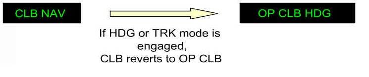
Lateral mode change and vertical mode reversion
In descent:
Lateral mode change and vertical mode reversion
This reversion to V/S (FPA) mode on the current V/S target
does not modify the pitch behavior of the aircraft.
It is the flight crew’s responsibility to adapt pitch, if necessary.
THE AIRCRAFT ENTERS A F-PLN DISCONTINUITY
NAV mode is lost, when entering a F-PLN discontinuity.
On the lateral axis, the aircraft reverts to HDG (or TRK) mode.
On the vertical axis, the same reversion (as the one indicated above) occurs.
THE PF MANUALLY FLIES THE AIRCRAFT WITH THE FD ON,
AND DOES NOT FOLLOW THE FD PITCH ORDERS
If the flight crew does not follow the FD pitch orders, an A/THR mode reversion occurs.
This reversion is effective, when the A/THR is in THRUST MODE (THR IDLE, THR CLB),
and the aircraft reaches the limits of the speed envelope (VLS, VMAX):
reversion to speed mode
AP, FD, A/THR MODE CHANGES AND REVERSIONS
Applicable to: MSN 4354, 4405, 4413, 4450, 4490, 4526
INTRODUCTION
The flight crew manually engages the modes.
However, they may change automatically, depending on the:
‐ AP, FD, and A/THR system integration
‐ Logical sequence of modes
‐ So-called "mode reversions".
AP, FD, ATHR SYSTEM INTEGRATION
There is a direct relationship between aircraft pitch control, and engine thrust control.
This relationship is designed to manage the aircraft’s energy.
‐ If the AP/FD pitch mode controls a vertical trajectory (e.g. ALT, V/S, FPA, G/S):
A/THR controls speed
‐ If the AP/FD pitch mode controls a speed (e.g. OP CLB, OP DES):
A/THR controls thrust (THR CLB, THR IDLE)
‐ If no AP/FD pitch mode is engaged (i.e. AP is off and FD is off):
A/THR controls speed
Therefore, any change in the AP/FD pitch mode is associated with a change in the A/THR mode.
Note:
For this reason, the FMA displays the A/THR mode and the AP/FD vertical mode
columns next to each other.
THE LOGICAL SEQUENCE OF MODES
In climb, when the flight crew selects a climb mode, they usually define an altitude target,
and expect the aircraft to capture and track this altitude.
Therefore, when the flight crew selects a climb mode, the next logical mode is automatically armed.
For example:
AP/FD Mode Capture and Tracking (1)
The flight crew may also manually arm a mode in advance,
so that the AP/FD intercepts a defined trajectory.
Typically, the flight crew may arm NAV, LOC-G/S and F-LOC-F-G/S.
When the capture or tracking conditions occur, the mode will change sequentially.
AP/FD Mode Capture and Tracking (2)
These logical mode changes occur, when the modes are armed. They appear in blue on the FMA
MODE REVERSIONS
GENERAL
Mode reversions are automatic mode changes that unexpectedly occur, but are designed to
ensure coherent AP, FD, and A/THR operations, in conjunction with flight crew input
(or when entering a F-PLN discontinuity).
For example, a reversion will occur, when the flight crew:
‐ Changes the FCU ALT target in specific conditions
‐ Engages a mode on 01 axis, that will automatically disengage
the associated mode on the other axis
‐ Manually flies the aircraft with the FD on, but does not follow the FD orders,
which leads to the aircraft to the limits of the flight envelope.
Due to the unexpected nature of their occurrence, the FMA should be closely-monitored for
mode reversions.
FLIGHT CREW CHANGE OF FCU ALT TARGET ▸ ACTIVE VERTICAL MODE NOT POSSIBLE
FCU Change Resulting Reversion to VS Mode
This reversion to the V/S (FPA) mode on the current V/S target does not modify the pitch
behaviour of the aircraft.
It is the flight crew's responsibility to change it as required.
FLIGHT CREW HDG OR TRK MODE ENGAGEMENT ▸
DISENGAGEMENT OF ASSOCIATEDMODE ON THE VERTICAL AXIS
This reversion is due to the integration of the AP, FD, and A/THR with the FMS.
When the flight crew defines a F-PLN, the FMS considers this F-PLN as
a whole (lateral + vertical).
Therefore, the AP will guide the aircraft along the entire F-PLN:
‐ Along the LAT F-PLN (NAV – F-LOC modes)
‐ Along the VERT F-PLN (CLB – DES –F-G/S modes).
Vertical managed modes can only be used, if the lateral managed NAV mode is used.
If the flight crew decides to divert from the lateral F-PLN,
the autopilot will no longer guide the aircraft along the vertical F-PLN.
Therefore, in climb:
Lateral Mode Change and Vertical Mode Reversion
In descent:
Lateral Mode Change and Vertical Mode Reversion
This reversion to V/S (FPA) mode on the current V/S target
does not modify the pitch behaviorof the aircraft.
It is the flight crew’s responsibility to adapt pitch, if necessary.
THE AIRCRAFT ENTERS A F-PLN DISCONTINUITY
NAV mode is lost, when entering a F-PLN discontinuity.
On the lateral axis, the aircraft reverts to HDG (or TRK) mode.
On the vertical axis, the same reversion (as the one indicated above)occurs.
THE PF MANUALLY FLIES THE AIRCRAFT WITH THE FD ON,
AND DOES NOT FOLLOW THE FD PITCH ORDERS
If the flight crew does not follow the FD pitch orders, an A/THR mode reversion occurs.
This reversion is effective, when the A/THR is in THRUST MODE (THR IDLE, THR CLB),
and the aircraft reaches the limits of the speed envelope (VLS, VMAX):
Reversion to Speed Mode
A/THR in SPEED mode automatically readjusts thrust to regain the target speed. The FD bars
will disappear, because they are not being followed by the PF.
TRIPLE CLICK
The "triple click" is an aural alert. It is an attention-getter,
designed to draw the flight crew's attentionto the FMA.
The PFD FMA highlights a mode change or reversion with a white box around the new mode,
and the pulsing of its associated FD bar.
The reversions, described in the previous paragraph, are also emphasized via the triple click aural
alert.
Note:
The triple click also appears in the following, less usual, cases:
• SRS ▸ CLB (OPCLB) reversion: If, the flight crew selects a speed on the FCU
• The V/S selection is "refused" during ALT *:
The flight crew pulls the V/S knob, while in ALT*
• The V/S target is not followed, because the selected target is too high,
and leads to VMIN/VMAX.
INTRODUCTION
The flight crew manually engages the modes.
However, they may change automatically, depending on the:
• AP, FD, and A/THR system integration
• Logical sequence of modes
• So-called "mode reversions".
AP, FD, ATHR SYSTEM INTEGRATION
There is a direct relationship between aircraft pitch control, and engine thrust control.
This relationship is designed to manage the aircraft’s energy.
• If the AP/FD pitch mode controls a vertical trajectory (e.g. ALT, V/S, FPA, G/S):
A/THR controls speed
• If the AP/FD pitch mode controls a speed (e.g. OP CLB, OP DES):
A/THR controls thrust (THR CLB, THR IDLE)
• If no AP/FD pitch mode is engaged (i.e. AP is off and FD is off):
A/THR controls speed
Therefore, any change in the AP/FD pitch mode is associated with a change in the A/THR mode.
Note:
For this reason, the FMA displays the A/THR mode and the AP/FD
vertical mode columns next to each other.
THE LOGICAL SEQUENCE OF MODES
In climb, when the flight crew selects a climb mode, they usually define an altitude target,
and expect the aircraft to capture and track this altitude.
Therefore, when the flight crew selects a climb mode,
the next logical mode is automatically armed.
For example:
AP/FD mode capture and tracking (1)
The flight crew may also manually arm a mode in advance,
so that the AP/FD intercepts a defined trajectory.
Typically, the flight crew may arm NAV, LOC-G/S, and APPNAV-FINAL.
When the capture or tracking conditions occur, the mode will change sequentially.
AP/FD mode capture and tracking (2)
These logical mode changes occur, when the modes are armed.
They appear in blue on the FMA.
MODE REVERSIONS
GENERAL
Mode reversions are automatic mode changes that unexpectedly occur, but are designed to
ensure coherent AP, FD, and A/THR operations, in conjunction with flight crew input
(or when entering a F-PLN discontinuity).
For example, a reversion will occur, when the flight crew:
• Changes the FCU ALT target in specific conditions
• Engages a mode on one axis, that will automatically disengage the associated mode
on the other axis
Due to the unexpected nature of their occurrence, the FMA should be closely-monitored for
mode reversions.
FLIGHT CREW CHANGE OF FCU ALT TARGET ▸ ACTIVE VERTICAL MODE NOT POSSIBLE
FCU change resulting reversion to VS mode
This reversion to the V/S (FPA) mode on the current V/S target does not modify the pitch
behaviour of the aircraft.
It is the flight crew's responsibility to change it as required.
FLIGHT CREW HDG OR TRK MODE ENGAGEMENT ▸ DISENGAGEMENT OF ASSOCIATED
MODE ON THE VERTICAL AXIS
This reversion is due to the integration of the AP, FD, and A/THR with the FMS.
When the flight crew defines a F-PLN, the FMS considers this F-PLN
as a whole (lateral + vertical).
Therefore, the AP will guide the aircraft along the entire F-PLN:
• Along the LAT F-PLN (NAV – APP NAV modes)
• Along the VERT F-PLN (CLB – DES – FINAL modes).
Vertical managed modes can only be used, if the lateral managed NAV mode is used.
If the flight crew decides to divert from the lateral F-PLN,
the autopilot will no longer guide the aircraft along the vertical F-PLN.
Therefore, in climb:
Lateral mode change and vertical mode reversion
In descent:
Lateral mode change and vertical mode reversion
This reversion to V/S (FPA) mode on the current V/S target
does not modify the pitch behavior of the aircraft.
It is the flight crew’s responsibility to adapt pitch, if necessary.
THE AIRCRAFT ENTERS A F-PLN DISCONTINUITY
NAV mode is lost, when entering a F-PLN discontinuity.
On the lateral axis, the aircraft reverts to HDG (or TRK) mode.
On the vertical axis, the same reversion (as the one indicated above) occurs.
THE PF MANUALLY FLIES THE AIRCRAFT WITH THE FD ON,
AND DOES NOT FOLLOW THE FD PITCH ORDERS
If the flight crew does not follow the FD pitch orders, an A/THR mode reversion occurs.
This reversion is effective, when the A/THR is in THRUST MODE (THR IDLE, THR CLB),
and the aircraft reaches the limits of the speed envelope (VLS, VMAX):
reversion to speed mode
AP, FD, A/THR MODE CHANGES AND REVERSIONS
Applicable to: MSN 4354, 4405, 4413, 4450, 4490, 4526
INTRODUCTION
The flight crew manually engages the modes.
However, they may change automatically, depending on the:
‐ AP, FD, and A/THR system integration
‐ Logical sequence of modes
‐ So-called "mode reversions".
AP, FD, ATHR SYSTEM INTEGRATION
There is a direct relationship between aircraft pitch control, and engine thrust control.
This relationship is designed to manage the aircraft’s energy.
‐ If the AP/FD pitch mode controls a vertical trajectory (e.g. ALT, V/S, FPA, G/S):
A/THR controls speed
‐ If the AP/FD pitch mode controls a speed (e.g. OP CLB, OP DES):
A/THR controls thrust (THR CLB, THR IDLE)
‐ If no AP/FD pitch mode is engaged (i.e. AP is off and FD is off):
A/THR controls speed
Therefore, any change in the AP/FD pitch mode is associated with a change in the A/THR mode.
Note:
For this reason, the FMA displays the A/THR mode and the AP/FD vertical mode
columns next to each other.
THE LOGICAL SEQUENCE OF MODES
In climb, when the flight crew selects a climb mode, they usually define an altitude target,
and expect the aircraft to capture and track this altitude.
Therefore, when the flight crew selects a climb mode, the next logical mode is automatically armed.
For example:
AP/FD Mode Capture and Tracking (1)
The flight crew may also manually arm a mode in advance,
so that the AP/FD intercepts a defined trajectory.
Typically, the flight crew may arm NAV, LOC-G/S and F-LOC-F-G/S.
When the capture or tracking conditions occur, the mode will change sequentially.
AP/FD Mode Capture and Tracking (2)
These logical mode changes occur, when the modes are armed. They appear in blue on the FMA
MODE REVERSIONS
GENERAL
Mode reversions are automatic mode changes that unexpectedly occur, but are designed to
ensure coherent AP, FD, and A/THR operations, in conjunction with flight crew input
(or when entering a F-PLN discontinuity).
For example, a reversion will occur, when the flight crew:
‐ Changes the FCU ALT target in specific conditions
‐ Engages a mode on 01 axis, that will automatically disengage
the associated mode on the other axis
‐ Manually flies the aircraft with the FD on, but does not follow the FD orders,
which leads to the aircraft to the limits of the flight envelope.
Due to the unexpected nature of their occurrence, the FMA should be closely-monitored for
mode reversions.
FLIGHT CREW CHANGE OF FCU ALT TARGET ▸ ACTIVE VERTICAL MODE NOT POSSIBLE
FCU Change Resulting Reversion to VS Mode
This reversion to the V/S (FPA) mode on the current V/S target does not modify the pitch
behaviour of the aircraft.
It is the flight crew's responsibility to change it as required.
FLIGHT CREW HDG OR TRK MODE ENGAGEMENT ▸
DISENGAGEMENT OF ASSOCIATEDMODE ON THE VERTICAL AXIS
This reversion is due to the integration of the AP, FD, and A/THR with the FMS.
When the flight crew defines a F-PLN, the FMS considers this F-PLN as
a whole (lateral + vertical).
Therefore, the AP will guide the aircraft along the entire F-PLN:
‐ Along the LAT F-PLN (NAV – F-LOC modes)
‐ Along the VERT F-PLN (CLB – DES –F-G/S modes).
Vertical managed modes can only be used, if the lateral managed NAV mode is used.
If the flight crew decides to divert from the lateral F-PLN,
the autopilot will no longer guide the aircraft along the vertical F-PLN.
Therefore, in climb:
Lateral Mode Change and Vertical Mode Reversion
In descent:
Lateral Mode Change and Vertical Mode Reversion
This reversion to V/S (FPA) mode on the current V/S target
does not modify the pitch behaviorof the aircraft.
It is the flight crew’s responsibility to adapt pitch, if necessary.
THE AIRCRAFT ENTERS A F-PLN DISCONTINUITY
NAV mode is lost, when entering a F-PLN discontinuity.
On the lateral axis, the aircraft reverts to HDG (or TRK) mode.
On the vertical axis, the same reversion (as the one indicated above)occurs.
THE PF MANUALLY FLIES THE AIRCRAFT WITH THE FD ON,
AND DOES NOT FOLLOW THE FD PITCH ORDERS
If the flight crew does not follow the FD pitch orders, an A/THR mode reversion occurs.
This reversion is effective, when the A/THR is in THRUST MODE (THR IDLE, THR CLB),
and the aircraft reaches the limits of the speed envelope (VLS, VMAX):
Reversion to Speed Mode
A/THR in SPEED mode automatically readjusts thrust to regain the target speed. The FD bars
will disappear, because they are not being followed by the PF.
TRIPLE CLICK
The "triple click" is an aural alert. It is an attention-getter,
designed to draw the flight crew's attentionto the FMA.
The PFD FMA highlights a mode change or reversion with a white box around the new mode,
and the pulsing of its associated FD bar.
The reversions, described in the previous paragraph, are also emphasized via the triple click aural
alert.
Note:
The triple click also appears in the following, less usual, cases:
• SRS ▸ CLB (OPCLB) reversion: If, the flight crew selects a speed on the FCU
• The V/S selection is "refused" during ALT *:
The flight crew pulls the V/S knob, while in ALT*
• The V/S target is not followed, because the selected target is too high,
and leads to VMIN/VMAX.
AUTOTHRUST (A/THR)
OBJECTIVE
The A/THR computer (within the FG) interfaces directly with the engine computer,
referred to as the FADEC.
The A/THR sends to the FADEC the thrust targets that are needed to:
• Obtain and maintain a target speed, when in SPEED mode
• Obtain a specific thrust setting (e.g. CLB, IDLE), when in THRUST mode.
INTERFACE
When the A/THR is active, the thrust lever position determines the maximum thrust
that the A/THR can command in SPEED or THRUST mode.
Therefore, with A/THR active, thrust levers act as a
thrust limiter or a thrust-rating panel.
The A/THR computer does not drive back the thrust levers.
The PF sets them to a specific detent on the thrust lever range.
The A/THR system provides cues that indicate the energy of the aircraft:
• Speed, acceleration, or deceleration, obtained by the speed trend vector
• N1, and N1 command on the N1 gauge.
All these cues are in the flight crew’s direct line of vision.
In other words, the Thrust Lever Angle (TLA) should not be used
to monitor correct A/THR operation.
Neither should the thrust lever position of a conventional autothrottle,
be considered a cue because, in many hazardous situations,
the thrust lever position can be misleading
(e.g. engine failure, thrust lever jammed).
the TLA determines Max thrust for the A/THR
NORMAL OPERATIONS
The A/THR can only be active, when the thrust levers are
between IDLE and the CLB detent.
When the thrust levers are beyond the CLB detent,
thrust is controlled manually to the thrust lever Angle,
and the A/THR is armed (A/THR appears in blue on the FMA).
This means that the A/THR is ready to be re-activated,
when the flight crew sets the thrust levers back to the CLB detent
(or below).
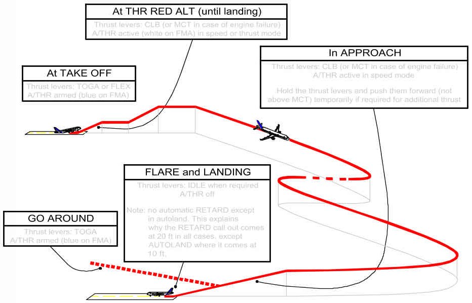
AT TAKEOFF
The thrust levers are set either full forward to TOGA, or to the FLX detent.
Thrust is manually controlled to the TLA, and A/THR is armed.
The FMA indicates this in blue.
AFTER TAKEOFF
When the aircraft reaches THR RED ALT, the flight crew sets the
thrust levers back to the CLB detent.
This activates A/THR.
MAX CLB will, therefore, be the maximum normal thrust setting
that will be commanded by the A/THR in CLB, CRZ, DES, or APPR, as required.
THRUST LEVER(S) BELOW THE CLB DETENT
If one thrust lever is set to below the CLB detent,
the FMA triggers a LVR ASYM message, as a reminder to the flight crew
(e.g. this configuration might be required due to an engine’s high vibration level).
However, if all thrust levers are set to below the CLB detent,
with the A/THR active, then CLB or LVR CLB flashes in the first FMA column.
This is because there is no operational reason to be in such a situation,
and to permanently limit A/THR authority on all engines.
In this case, all thrust levers should either be brought back to the CLB detent,
or the A/THR should be set to OFF.
OPERATIONS WITH ONE ENGINE INOPERATIVE
The above-noted principles also apply to an one-engine inoperative situation,
except that A/THR can only be active, when thrust levers are set between IDLE and MCT.
A/THR operating technique: one engine inoperative
In case of engine failure, the thrust levers will be
in MCT detent for remainder of the flight.
This is because MCT is the maximum thrust that can usually be commanded
by the A/THR for climb or acceleration, in all flight phases
(e.g. CLB, CRZ, DES or APPR ).
TO SET AUTOTHRUST TO OFF
How to set A/THR off
1) USE OF INSTINCTIVE DISCONNECT (I/D) PUSHBUTTON
If the I/D pushbutton is pressed when the thrust levers are in CL detent,
thrust will increase to MAX CL.
This will cause an unwanted thrust increase and may destabilize the approach.
Therefore, the recommended technique for setting A/THR to off is:
‐ Return the thrust levers to approximately the current thrust setting,
by observing the TLA symbol on the thrust gauge
‐ Press the I/D pushbutton
This technique minimizes thrust discontinuity, when setting A/THR to off.
recommended technique to set A/THR to off
2) THRUST LEVERS SET TO IDLE
If thrust levers are set to IDLE, A/THR is set to off.
This technique is usually used in descent,
when the A/THR is in THR IDLE, or at landing.
During flare, with the A/THR active, the thrust levers are set to the CLB detent.
Then, when thrust reduction is required for landing,
the thrust levers should be moved rapidly and set to the IDLE stop.
This will retard thrust, and set A/THR to off.
As a reminder, the "RETARD" aural alert will sound.
In flare, this aural alert will occur at 20 ft, except in the case of autoland,
where it occurs at 10 ft.
It should be noted that, when the thrust levers are set back to IDLE and A/THR set to off:
The A/THR can be reactivated by pressing the pushbutton on the FCU, and returning the
thrust levers to the applicable detent.
The thrust levers should be immediately returned to the applicable detent,
in order to avoid flashing CLB or LVR CLB message on the first FMA column.
3) USE OF THE FCU PUSHBUTTON
Use of the FCU pushbutton is considered to be an involuntary A/THR off command
(e.g. in the case of a failure).
When pressed, thrust is frozen and remains locked at the value it had when
the flight crew pressed the A/THR pushbutton, as long as
the thrust levers remain in the CLB or MCT detent.
If thrust levers are out of detent, thrust is manually controlled and, therefore, unlocked.
A THR LK message appears in amber on the FMA.
In this case, when the flight crew moves the thrust levers out of detent, full manual control is
recovered, and the THR LK message disappears from the FMA.
This feature should not be used, unless the instinctive disconnect pushbuttons are inoperative.
ALPHA FLOOR
When the aircraft's angle-of-attack goes beyond the ALPHA FLOOR threshold, this means that the
aircraft has decelerated significantly (below ALPHA PROT speed):
A/THR activates automatically and orders TOGA thrust,
regardless of the thrust lever position.
The example below illustrates that:
• The aircraft is in descent with the thrust levers manually set to IDLE.
• The aircraft decelerates, during manual flight with the FD off, as indicated on the FMA.
Speed scale and FMA indication in a typical A Floor Case
When the speed decreases, so that the angle-of-attack reaches the ALPHA FLOOR threshold,
A/THR activates and orders TOGA thrust, despite the fact that the thrust levers are at IDLE.
When the aircraft accelerates again, the angle-of-attack drops below
the ALPHA FLOOR threshold.
TOGA thrust is maintained or locked.
This enables the flight crew to reduce thrust, as necessary.
TOGA LK appears on the FMA to indicate that TOGA thrust is locked.
The desired thrust can only be recovered by setting A/THR to off,
with the instinctive disconnect pushbutton.
ALPHA floor is available, when the flight controls are in NORMAL LAW, from liftoff
to 100 ft RA at landing.
It is inhibited in some cases of engine failure.
A/THR USE - SUMMARY
Use of A/THR is recommended during the entire flight. It may be used in most failures cases,
including:
• Engine failure, even during autoland
• Abnormal configurations
A/THR should be monitored via the:
• FMA – SPEED / SPEED TREND on the PFD
• N1/N1 command (EPR) on the ECAM E/WD.
OBJECTIVE
The A/THR computer (within the FG) interfaces directly with the engine computer,
referred to as the FADEC.
The A/THR sends to the FADEC the thrust targets that are needed to:
• Obtain and maintain a target speed, when in SPEED mode
• Obtain a specific thrust setting (e.g. CLB, IDLE), when in THRUST mode.
INTERFACE
When the A/THR is active, the thrust lever position determines the maximum thrust
that the A/THR can command in SPEED or THRUST mode.
Therefore, with A/THR active, thrust levers act as a
thrust limiter or a thrust-rating panel.
The A/THR computer does not drive back the thrust levers.
The PF sets them to a specific detent on the thrust lever range.
The A/THR system provides cues that indicate the energy of the aircraft:
• Speed, acceleration, or deceleration, obtained by the speed trend vector
• N1, and N1 command on the N1 gauge.
All these cues are in the flight crew’s direct line of vision.
In other words, the Thrust Lever Angle (TLA) should not be used
to monitor correct A/THR operation.
Neither should the thrust lever position of a conventional autothrottle,
be considered a cue because, in many hazardous situations,
the thrust lever position can be misleading
(e.g. engine failure, thrust lever jammed).
the TLA determines Max thrust for the A/THR
NORMAL OPERATIONS
The A/THR can only be active, when the thrust levers are
between IDLE and the CLB detent.
When the thrust levers are beyond the CLB detent,
thrust is controlled manually to the thrust lever Angle,
and the A/THR is armed (A/THR appears in blue on the FMA).
This means that the A/THR is ready to be re-activated,
when the flight crew sets the thrust levers back to the CLB detent
(or below).
AT TAKEOFF
The thrust levers are set either full forward to TOGA, or to the FLX detent.
Thrust is manually controlled to the TLA, and A/THR is armed.
The FMA indicates this in blue.
AFTER TAKEOFF
When the aircraft reaches THR RED ALT, the flight crew sets the
thrust levers back to the CLB detent.
This activates A/THR.
MAX CLB will, therefore, be the maximum normal thrust setting
that will be commanded by the A/THR in CLB, CRZ, DES, or APPR, as required.
THRUST LEVER(S) BELOW THE CLB DETENT
If one thrust lever is set to below the CLB detent,
the FMA triggers a LVR ASYM message, as a reminder to the flight crew
(e.g. this configuration might be required due to an engine’s high vibration level).
However, if all thrust levers are set to below the CLB detent,
with the A/THR active, then CLB or LVR CLB flashes in the first FMA column.
This is because there is no operational reason to be in such a situation,
and to permanently limit A/THR authority on all engines.
In this case, all thrust levers should either be brought back to the CLB detent,
or the A/THR should be set to OFF.
OPERATIONS WITH ONE ENGINE INOPERATIVE
The above-noted principles also apply to an one-engine inoperative situation,
except that A/THR can only be active, when thrust levers are set between IDLE and MCT.
A/THR operating technique: one engine inoperative
In case of engine failure, the thrust levers will be
in MCT detent for remainder of the flight.
This is because MCT is the maximum thrust that can usually be commanded
by the A/THR for climb or acceleration, in all flight phases
(e.g. CLB, CRZ, DES or APPR ).
TO SET AUTOTHRUST TO OFF
How to set A/THR off
1) USE OF INSTINCTIVE DISCONNECT (I/D) PUSHBUTTON
If the I/D pushbutton is pressed when the thrust levers are in CL detent,
thrust will increase to MAX CL.
This will cause an unwanted thrust increase and may destabilize the approach.
Therefore, the recommended technique for setting A/THR to off is:
‐ Return the thrust levers to approximately the current thrust setting,
by observing the TLA symbol on the thrust gauge
‐ Press the I/D pushbutton
This technique minimizes thrust discontinuity, when setting A/THR to off.
recommended technique to set A/THR to off
2) THRUST LEVERS SET TO IDLE
If thrust levers are set to IDLE, A/THR is set to off.
This technique is usually used in descent,
when the A/THR is in THR IDLE, or at landing.
During flare, with the A/THR active, the thrust levers are set to the CLB detent.
Then, when thrust reduction is required for landing,
the thrust levers should be moved rapidly and set to the IDLE stop.
This will retard thrust, and set A/THR to off.
As a reminder, the "RETARD" aural alert will sound.
In flare, this aural alert will occur at 20 ft, except in the case of autoland,
where it occurs at 10 ft.
It should be noted that, when the thrust levers are set back to IDLE and A/THR set to off:
The A/THR can be reactivated by pressing the pushbutton on the FCU, and returning the
thrust levers to the applicable detent.
The thrust levers should be immediately returned to the applicable detent,
in order to avoid flashing CLB or LVR CLB message on the first FMA column.
3) USE OF THE FCU PUSHBUTTON
Use of the FCU pushbutton is considered to be an involuntary A/THR off command
(e.g. in the case of a failure).
When pressed, thrust is frozen and remains locked at the value it had when
the flight crew pressed the A/THR pushbutton, as long as
the thrust levers remain in the CLB or MCT detent.
If thrust levers are out of detent, thrust is manually controlled and, therefore, unlocked.
A THR LK message appears in amber on the FMA.
In this case, when the flight crew moves the thrust levers out of detent, full manual control is
recovered, and the THR LK message disappears from the FMA.
This feature should not be used, unless the instinctive disconnect pushbuttons are inoperative.
ALPHA FLOOR
When the aircraft's angle-of-attack goes beyond the ALPHA FLOOR threshold, this means that the
aircraft has decelerated significantly (below ALPHA PROT speed):
A/THR activates automatically and orders TOGA thrust,
regardless of the thrust lever position.
The example below illustrates that:
• The aircraft is in descent with the thrust levers manually set to IDLE.
• The aircraft decelerates, during manual flight with the FD off, as indicated on the FMA.
Speed scale and FMA indication in a typical A Floor Case
When the speed decreases, so that the angle-of-attack reaches the ALPHA FLOOR threshold,
A/THR activates and orders TOGA thrust, despite the fact that the thrust levers are at IDLE.
When the aircraft accelerates again, the angle-of-attack drops below
the ALPHA FLOOR threshold.
TOGA thrust is maintained or locked.
This enables the flight crew to reduce thrust, as necessary.
TOGA LK appears on the FMA to indicate that TOGA thrust is locked.
The desired thrust can only be recovered by setting A/THR to off,
with the instinctive disconnect pushbutton.
ALPHA floor is available, when the flight controls are in NORMAL LAW, from liftoff
to 100 ft RA at landing.
It is inhibited in some cases of engine failure.
A/THR USE - SUMMARY
Use of A/THR is recommended during the entire flight. It may be used in most failures cases,
including:
• Engine failure, even during autoland
• Abnormal configurations
A/THR should be monitored via the:
• FMA – SPEED / SPEED TREND on the PFD
• N1/N1 command (EPR) on the ECAM E/WD.
MECHANICAL BACKUP
Applicable to: ALL
The purpose of the mechanical backup is to achieve all safety objectives
in MMEL dispatch condition:
To manage a temporary and total electrical loss,
the temporary loss of five fly-by-wire computers,
the loss of both elevators,
or the total loss of ailerons and spoilers.
It must be noted that it is very unlikely that
the mechanical backup will be used, due to the
fly-by-wire architecture. For example, in case of
electrical emergency configuration, or an all-engine
flameout, alternate law remains available.
In the unlikely event of such a failure,
mechanical backup enables the PF to safely stabilize the
aircraft, using the rudder and manual pitch trim,
while reconfiguring the systems
In such cases, the objective is not to fly the aircraft accurately,
but to maintain the aircraft attitude safe and stabilized,
in order to allow the restoration of lost systems.
The pitch trim wheel is used to control pitch.
Any action on the pitch trim wheel should be applied
smoothly, because the THS effect is significant due to its large size.
The rudder provides lateral control, and induces
a significant roll with a slight delay.
The PF should apply some rudder to turn, and wait for the aircraft reaction.
To stabilize and level the wings,
anticipate by releasing the rudder pedals.
A red “MAN PITCH TRIM ONLY” message appears on the PFD
to immediately inform the PF that the
mechanical backup is being used.
back-up indication on PFD
ABNORMAL ATTITUDES
Applicable to: ALL
If the aircraft is, for any reason, far outside
the normal flight envelope and reaches an abnormal
attitude, the normal controls are modified
and provide the PF with maximum efficiency in regaining
normal attitudes.
(An example of a typical reason for being far outside the
normal flight envelope would be the avoidance of a mid-air collision).
The so-called "abnormal attitude" law is :
• Pitch alternate with load factor protection (without autotrim)
• Lateral direct law with yaw alternate
These laws trigger, when extreme values are reached:
• Pitch (50 ° up, 30 ° down)
• Bank (125 °)
• AOA (30 °, -10 °)
• Speed (440 kt, 60 kt)
• Mach (0.96, 0.1).
It is very unlikely that the aircraft will reach these attitudes,
because fly-by-wire provides protection to
ensure rapid reaction far in advance.
This will minimize the effect and potential
for such aerodynamic upsets.
The effectiveness of fly-by-wire architecture,
and the existence of control laws, eliminate the need for
upset recovery maneuvers to be trained on protected Airbus aircraft.
SIDESTICK AND TAKEOVER P/B
Applicable to: ALL
When the Pilot Flying (PF) makes an input on the sidestick,
an order (an electrical signal) is sent to the fly-by-wire computer.
If the Pilot Not Flying (PNF) also acts on the stick,
then both signals/orders are added.
Therefore, as on any other aircraft type,
PF and PNF must not act on their sidesticks at the same time.
If the PNF (or Instructor) needs to take over,
the PNF must press the sidestick takeover pushbutton,
and announce: "I have control".
If a flight crewmember falls on a sidestick, or a mechanical failure leads
to a jammed stick (there is no associate ECAM caution),
the "failed" sidestick order is added to the "non failed" sidestick order.
In this case, the other not affected flight crewmember
must press the sidestick takeover pushbutton for at least 40 s,
in order to deactivate the "failed" sidestick.
A pilot can at any time reactivate a deactivated stick
by momentarily pressing the takeover pushbutton on either stick.
In case of a "SIDE STICK FAULT" ECAM warning, due to an electrical failure,
the affected sidestick order (sent to the computer) is forced to zero.
This automatically deactivates the affected sidestick.
This explains why there is no procedure associated with this warning.
AUTOPILOT/FLIGHT DIRECTOR
OBJECTIVE
The Auto Pilot (AP) and Flight Director (FD) assist the flight crew
to fly the aircraft within the normal flight envelope, in order to:
• Optimize performance in the takeoff, go-around, climb, or descent phases
• Follow ATC clearances (lateral or vertical)
• Repeatedly fly and land the aircraft with very high accuracy
in CAT II and CAT III conditions.
To achieve these objectives:
• The AP takes over routine tasks. This gives the Pilot Flying (PF)
the necessary time and resources to assess the overall operational situation.
• The FD provides adequate attitude or flight path orders, and enables the PF
to accurately fly the aircraft manually.
MANAGED AND SELECTED MODES
The choice of mode is a strategic decision that is taken by the PF.
Managed modes require:
• Good FMS navigation accuracy (or GPS PRIMARY)
• An appropriate ACTIVE F-PLN
(i.e. the intended lateral and vertical trajectory is entered, and
the sequencing of the F-PLN is monitored).
MAIN INTERFACES WITH THE AP/FD
*The DIR TO function is an exception to this rule.
OPERATIONAL RECOMMENDATION:
With the FMS, anticipate flight plan updates by preparing:
• EN ROUTE DIVERSIONS
• DIVERSION TO ALTN
• CIRCLING
• LATE CHANGE OF RWY in the SEC F-PLN.
This enables the MCDU to be used for short-term actions.
TASKSHARING AND COMMUNICATIONS
The FCU and MCDU must be used, in accordance with the rules outlined below,
in order to ensure:
• Safe operation (correct entries made)
• Effective inter-pilot communication (knowing each other's intentions)
• Comfortable operations (use "available hands", as appropriate)
AP/FD MONITORING
The FMA indicates the status of the AP, FD, and A/THR,
and their corresponding operating modes.
The PF must monitor the FMA, and announce any FMA changes.
The flight crew uses the FCU or MCDU to give orders to the AP/FD.
The aircraft is expected to fly in accordance with these orders.
The main concern for the flight crew should be:
WHAT IS THE AIRCRAFT EXPECTED TO FLY NOW ?
WHAT IS THE AIRCRAFT EXPECTED TO FLY NEXT ?
If the aircraft does not fly as expected:
‐ Or, disengage the AP, and fly the aircraft manually.
AUTOPILOT (AP) OPERATION
The AP can be engaged within the normal flight envelope,
5 s after liftoff and at least 100 ft.
It automatically disengages, when the aircraft flies
significantly outside the normal flight envelope limits.
The AP cannot be engaged, when the aircraft is outside the flight envelope.
Flight control laws are designed to assist the flight crew to
return within the flight envelope, in accordance with the selected strategy.
The AP may be used:
• For autoland: Down to the aircraft landing rollout,
in accordance with the limitations indicated in the FCOM
• For other approaches, down to:
‐ The MDA for straight in Non Precision Approach
‐ The DA for straight in LNAV/VNAV approach
‐ MDA - 100 ft for circling approach
‐ 160 ft for ILS approach with CAT1 displayed on FMA
‐ 500 ft for all others phases.
It may also be used, in case of:
• Engine failure: Without any restriction,
within the demonstrated limits, including autoland
• Abnormal configuration (e.g. slats/flaps failure):
Down to 500 ft AGL. Extra vigilance is required in these configurations.
The flight crew must be ready to take over, if the aircraft
deviates from its intended, safe flight path.
The sidestick's instinctive disconnect pushbutton should be used to disengage the AP.
Instinctive override action on the sidestick also disengages the AP.
It consists in pushing or pulling the sidestick beyond a given threshold.
The flight crew should use the FCU AP pushbutton when they
perform an AP switching (changeover from AP1(2) to AP2(1)).
RECOMMENDED PRACTICE FOR AUTOPILOT ENGAGEMENT
Before engaging the Autopilot (AP), the Flight Crew should:
‐ Fly the aircraft on the intended path
‐ Check on FMA that Flight Director (FD) is engaged
with the appropriate guidance modes for the intended flight path;
if not, select FD ON, and the appropriate guidance mode(s) as required
‐ Center the FD bars with the aircraft symbol on the PFD
Note:
Engaging the AP while large orders are required to achieve the intended flight path
may result in the AP overshooting the intended vertical and/or lateral target.
This situation may surprise the pilot due to the resulting
large pitch / roll changes and thrust variations.
USE OF THE FD WITHOUT THE AP
When manually flying the aircraft with the FDs on,
the FD bars or the FPD symbol provide lateral and vertical orders,
in accordance with the active modes that the flight crew selects.
Therefore:
‐ Fly with a centered FD or FPD
‐ If not using FD orders, turn off the FD.
It is strongly recommended to turn off both FDs,
to ensure that the A/THR is in SPEED mode, if
the A/THR is active.
Applicable to: ALL
The purpose of the mechanical backup is to achieve all safety objectives
in MMEL dispatch condition:
To manage a temporary and total electrical loss,
the temporary loss of five fly-by-wire computers,
the loss of both elevators,
or the total loss of ailerons and spoilers.
It must be noted that it is very unlikely that
the mechanical backup will be used, due to the
fly-by-wire architecture. For example, in case of
electrical emergency configuration, or an all-engine
flameout, alternate law remains available.
In the unlikely event of such a failure,
mechanical backup enables the PF to safely stabilize the
aircraft, using the rudder and manual pitch trim,
while reconfiguring the systems
In such cases, the objective is not to fly the aircraft accurately,
but to maintain the aircraft attitude safe and stabilized,
in order to allow the restoration of lost systems.
The pitch trim wheel is used to control pitch.
Any action on the pitch trim wheel should be applied
smoothly, because the THS effect is significant due to its large size.
The rudder provides lateral control, and induces
a significant roll with a slight delay.
The PF should apply some rudder to turn, and wait for the aircraft reaction.
To stabilize and level the wings,
anticipate by releasing the rudder pedals.
A red “MAN PITCH TRIM ONLY” message appears on the PFD
to immediately inform the PF that the
mechanical backup is being used.
back-up indication on PFD
ABNORMAL ATTITUDES
Applicable to: ALL
If the aircraft is, for any reason, far outside
the normal flight envelope and reaches an abnormal
attitude, the normal controls are modified
and provide the PF with maximum efficiency in regaining
normal attitudes.
(An example of a typical reason for being far outside the
normal flight envelope would be the avoidance of a mid-air collision).
The so-called "abnormal attitude" law is :
• Pitch alternate with load factor protection (without autotrim)
• Lateral direct law with yaw alternate
These laws trigger, when extreme values are reached:
• Pitch (50 ° up, 30 ° down)
• Bank (125 °)
• AOA (30 °, -10 °)
• Speed (440 kt, 60 kt)
• Mach (0.96, 0.1).
It is very unlikely that the aircraft will reach these attitudes,
because fly-by-wire provides protection to
ensure rapid reaction far in advance.
This will minimize the effect and potential
for such aerodynamic upsets.
The effectiveness of fly-by-wire architecture,
and the existence of control laws, eliminate the need for
upset recovery maneuvers to be trained on protected Airbus aircraft.
SIDESTICK AND TAKEOVER P/B
Applicable to: ALL
When the Pilot Flying (PF) makes an input on the sidestick,
an order (an electrical signal) is sent to the fly-by-wire computer.
If the Pilot Not Flying (PNF) also acts on the stick,
then both signals/orders are added.
Therefore, as on any other aircraft type,
PF and PNF must not act on their sidesticks at the same time.
If the PNF (or Instructor) needs to take over,
the PNF must press the sidestick takeover pushbutton,
and announce: "I have control".
If a flight crewmember falls on a sidestick, or a mechanical failure leads
to a jammed stick (there is no associate ECAM caution),
the "failed" sidestick order is added to the "non failed" sidestick order.
In this case, the other not affected flight crewmember
must press the sidestick takeover pushbutton for at least 40 s,
in order to deactivate the "failed" sidestick.
A pilot can at any time reactivate a deactivated stick
by momentarily pressing the takeover pushbutton on either stick.
In case of a "SIDE STICK FAULT" ECAM warning, due to an electrical failure,
the affected sidestick order (sent to the computer) is forced to zero.
This automatically deactivates the affected sidestick.
This explains why there is no procedure associated with this warning.
AUTOPILOT/FLIGHT DIRECTOR
OBJECTIVE
The Auto Pilot (AP) and Flight Director (FD) assist the flight crew
to fly the aircraft within the normal flight envelope, in order to:
• Optimize performance in the takeoff, go-around, climb, or descent phases
• Follow ATC clearances (lateral or vertical)
• Repeatedly fly and land the aircraft with very high accuracy
in CAT II and CAT III conditions.
To achieve these objectives:
• The AP takes over routine tasks. This gives the Pilot Flying (PF)
the necessary time and resources to assess the overall operational situation.
• The FD provides adequate attitude or flight path orders, and enables the PF
to accurately fly the aircraft manually.
MANAGED AND SELECTED MODES
The choice of mode is a strategic decision that is taken by the PF.
Managed modes require:
• Good FMS navigation accuracy (or GPS PRIMARY)
• An appropriate ACTIVE F-PLN
(i.e. the intended lateral and vertical trajectory is entered, and
the sequencing of the F-PLN is monitored).
MAIN INTERFACES WITH THE AP/FD
*The DIR TO function is an exception to this rule.
OPERATIONAL RECOMMENDATION:
With the FMS, anticipate flight plan updates by preparing:
• EN ROUTE DIVERSIONS
• DIVERSION TO ALTN
• CIRCLING
• LATE CHANGE OF RWY in the SEC F-PLN.
This enables the MCDU to be used for short-term actions.
TASKSHARING AND COMMUNICATIONS
The FCU and MCDU must be used, in accordance with the rules outlined below,
in order to ensure:
• Safe operation (correct entries made)
• Effective inter-pilot communication (knowing each other's intentions)
• Comfortable operations (use "available hands", as appropriate)
AP/FD MONITORING
The FMA indicates the status of the AP, FD, and A/THR,
and their corresponding operating modes.
The PF must monitor the FMA, and announce any FMA changes.
The flight crew uses the FCU or MCDU to give orders to the AP/FD.
The aircraft is expected to fly in accordance with these orders.
The main concern for the flight crew should be:
WHAT IS THE AIRCRAFT EXPECTED TO FLY NOW ?
WHAT IS THE AIRCRAFT EXPECTED TO FLY NEXT ?
If the aircraft does not fly as expected:
‐ Or, disengage the AP, and fly the aircraft manually.
AUTOPILOT (AP) OPERATION
The AP can be engaged within the normal flight envelope,
5 s after liftoff and at least 100 ft.
It automatically disengages, when the aircraft flies
significantly outside the normal flight envelope limits.
The AP cannot be engaged, when the aircraft is outside the flight envelope.
Flight control laws are designed to assist the flight crew to
return within the flight envelope, in accordance with the selected strategy.
The AP may be used:
• For autoland: Down to the aircraft landing rollout,
in accordance with the limitations indicated in the FCOM
• For other approaches, down to:
‐ The MDA for straight in Non Precision Approach
‐ The DA for straight in LNAV/VNAV approach
‐ MDA - 100 ft for circling approach
‐ 160 ft for ILS approach with CAT1 displayed on FMA
‐ 500 ft for all others phases.
It may also be used, in case of:
• Engine failure: Without any restriction,
within the demonstrated limits, including autoland
• Abnormal configuration (e.g. slats/flaps failure):
Down to 500 ft AGL. Extra vigilance is required in these configurations.
The flight crew must be ready to take over, if the aircraft
deviates from its intended, safe flight path.
The sidestick's instinctive disconnect pushbutton should be used to disengage the AP.
Instinctive override action on the sidestick also disengages the AP.
It consists in pushing or pulling the sidestick beyond a given threshold.
The flight crew should use the FCU AP pushbutton when they
perform an AP switching (changeover from AP1(2) to AP2(1)).
RECOMMENDED PRACTICE FOR AUTOPILOT ENGAGEMENT
Before engaging the Autopilot (AP), the Flight Crew should:
‐ Fly the aircraft on the intended path
‐ Check on FMA that Flight Director (FD) is engaged
with the appropriate guidance modes for the intended flight path;
if not, select FD ON, and the appropriate guidance mode(s) as required
‐ Center the FD bars with the aircraft symbol on the PFD
Note:
Engaging the AP while large orders are required to achieve the intended flight path
may result in the AP overshooting the intended vertical and/or lateral target.
This situation may surprise the pilot due to the resulting
large pitch / roll changes and thrust variations.
USE OF THE FD WITHOUT THE AP
When manually flying the aircraft with the FDs on,
the FD bars or the FPD symbol provide lateral and vertical orders,
in accordance with the active modes that the flight crew selects.
Therefore:
‐ Fly with a centered FD or FPD
‐ If not using FD orders, turn off the FD.
It is strongly recommended to turn off both FDs,
to ensure that the A/THR is in SPEED mode, if
the A/THR is active.
sexta-feira, 18 de novembro de 2011
LOAD FACTOR PROTECTION
On commercial aircraft, high load factors can be
encountered during evasive maneuvers due to potential collisions,
or CFIT …
Pulling "g" is efficient, if the resulting maneuver
is really flown with this "g" number.
If the aircraft is not able to fly this trajectory,
or to perform this maneuver, pulling "g" will be detrimental.
On commercial aircraft, the maximum load that is structurally allowed is:
• 2.5 g in clean configuration,
• 2.0 g with the flaps extended.
AIRBUS LOAD FACTOR PROTECTION and safety
On most commercial aircraft, the potential
for an efficient 2.5 g maneuver is very remote.
Furthermore, as G Load information is not continuously
provided in the cockpit, airline pilots are
not used to controlling this parameter.
This is further evidenced by inflight experience, which
reveals that: In emergency situations, initial PF reaction
on a yoke or sidestick is hesitant, then aggressive.
With load factor protection, the PF may immediately and
instinctively pull the sidestick full aft:
The aircraft will initially fly a 2.5 g maneuver without losing time.
Then, if the PF still needs to maintain the sidestick full aft stick,
because the danger still exists, then the high AOA protection will take over.
Load factor protection enhances this high AOA protection.
Load factor protection enables immediate PF reaction,
without any risk of overstressing the aircraft.
Flight experience has also revealed that an immediate 2.5 g reaction
provides larger obstacle clearance, than a hesitant
and delayed high G Load maneuver (two-second delay).
HIGH PITCH ATTITUDE PROTECTION
Excessive pitch attitudes, caused by upsets or
inappropriate maneuvers, lead to hazardous situations:
• Too high a nose-up ▸ Very rapid energy loss
• Too low a nose-down ▸ Very rapid energy gain
Furthermore, there is no emergency situation that
requires flying at excessive attitudes.
For these reasons, pitch attitude protection
limits pitch attitude to plus 30 °/minus 15 °.
Pitch attitude protection enhances high speed protection,
high load factor protection, and high AOA protection.
HIGH ANGLE-OF-ATTACK (AOA) PROTECTION
High AOA protection enables the PF to pull the sidestick full aft
in dangerous situations, and thus consistently achieve
the best possible aircraft lift.
This action on the sidestick is instinctive, and the
high AOA protection minimizes the risk of stalls or control loss.
High AOA protection is an aerodynamic protection:
• The PF will notice if the normal flight envelope is exceeded
for any reason, because the autopitch trim will stop,
the aircraft will sink to maintain its current AOA (alpha PROT, strong
static stability), and a significant change
in aircraft behavior will occur.
• If the PF then pulls the sidestick full aft,
a maximum AOA (approximately corresponding to CL Max) is commanded.
In addition, the speedbrakes will automatically retract, if extended.
airbus AOA PROTECTION
In addition to this aerodynamic protection, there are
three more energy features:
• If ATHR is in SPEED mode, the speed cannot drop below VLS,
even if the target speed is below VLS
• If the angle-of-attack still increases and reaches
ALPHA Floor threshold, the A/THR triggers TOGA thrust and
engages (unless in some cases of one engine-out).
In case of an emergency situation, such as Windshear or CFIT,
the PF is assisted in order to optimize aircraft performance via the:
• A/THR: Adds thrust to maintain the speed above VLS
• ALPHA FLOOR: Provides TOGA thrust
• HIGH AOA protection: Provides maximum aerodynamic lift
• Automatic speedbrake retraction: Minimizes drag.
OPERATIONAL RECOMMENDATIONS:
When flying at alpha max, the PF can make gentle turns, if necessary.
The PF must not deliberately fly the aircraft in alpha protection,
except for brief periods, when maximum maneuvering speed is required.
If alpha protection is inadvertently entered, the PF must exit
it as quickly as possible, by easing the sidestick forward
to reduce the angle-of-attack, while simultaneously adding power
(if alpha floor has not yet been activated, or has been cancelled).
If alpha floor has been triggered, it must be cancelled with
the instinctive disconnect pushbutton (on either thrust lever),
as soon as a safe speed is resumed.
In case of GPWS/SHEAR:
• Set the thrust levers to TOGA
• Pull the sidestick to full aft
(For shear, fly the SRS, until full aft sidestick).
• Initially maintain the wings level
This immediately provides maximum lift/maximum thrust/minimum drag.
Therefore, CFIT escape maneuvers will be much more efficient.
PROTECTED A/C VERSUS NON PROTECTED A/C GO-AROUND TRAJECTORY
The above-illustrated are typical trajectories flown
by all protected or not protected aircraft, when the PF applies
the escape procedure after an aural “ GPWS PULL UP” alert.
The graph demonstrates the efficiency of the protection,
to ensure a duck-under that is 50 % lower, a bucket-distance
that is 50 % shorter, a safety margin that more than doubles
(due to a quicker reaction time),
and a significant altitude gain (± 250 ft).
These characteristics are common to all protected aircraft,
because the escape procedure is easy to achieve, and enables
the PF to fly the aircraft at a constant AOA, close to the max AOA.
It is much more difficult to fly
the stick shaker AOA on an aircraft that is not protected.
PROTECTIONS
OBJECTIVES
One of the PF's primary tasks is to maintain the aircraft
within the limits of the normal flight envelope.
However, some circumstances, due to extreme situations
or aircraft mishandling, may provoke the violation of these limits.
Despite system protections, the PF must
not deliberately exceed the normal flight envelope.
In addition, these protections are not designed to be structural
limit protections (e.g. opposite rudder pedal inputs).
Rather, they are designed to assist the PF in
emergency and stressful situations, where only instinctive
and rapid reactions will be effective.
Protections are intended to:
• Provide full authority to the PF to consistently achieve
the best possible aircraft performance in extreme conditions
• Reduce the risks of overcontrolling, or overstressing the aircraft
• Provide PF with an instinctive and immediate procedure
to ensure that the PF achieves the best possible result.
BANK ANGLE PROTECTION
Bank angle protection prevents that any major upset,
or PF mishandling, causes the aircraft to be in a high-bank situation
(wherein aircraft recovery is complex, due to the difficulty to properly
assess such a situation and readily react).
Bank angle protection provides the PF with full authority
to efficiently achieve any required roll maneuver.
The maximum achievable bank angle is plus or minus:
• 67 °, within the Normal Flight envelope (2.5 g level flight)
• 40 °, in high Speed protection (to prevent spiral dive)
• 45 °, in high Angle-Of-Attack protection
HIGH SPEED PROTECTION
When flying beyond maximum design speeds VD/MD (which are greater that VMO/MMO),
there is an increased potential for aircraft control difficulties
and structural concerns, due to high air loads.
Therefore, the margin between VMO/MMO and VD/MD must
be such that any possible overshoot of the normal flight envelope
should not cause any major difficulty.
High speed protection adds a positive nose-up G demand to a sidestick order,
in order to protect the aircraft, in the event of a dive or vertical upset.
As a result, this enables a reduction in the margin betwen VMO/MMO and VD/MD.
Therefore, in a dive situation:
• If there is no sidestick input on the sidestick, the aircraft
will slightly overshoot VMO/MMO and fly back towards the envelope.
• If the sidestick is maintained full forward, the aircraft will
significantly overshoot VMO/MMO without reaching VD/MD.
At approximately VMO +16 / MMO +0.04, the pitch nose-down
authority smoothly reduces to zero (which does not mean that
the aircraft stabilizes at that speed).
airbus HIGH SPEED PROTECTION
The PF, therefore, has full authority to perform a high speed/steep
dive escape maneuver, when required, via a reflex action on the sidestick.
Note:
1. An OVERSPEED warning is provided.
2. At high altitude, this may result in activation of
the angle of attack protection.
Depending on the ELAC standard, the crew may have to
push on the stick to get out of this protection law.
DIRECT LAW
In most triple failure cases, direct law triggers.
When this occurs:
• Elevator deflection is proportional to stick deflection.
Maximum deflection depends on the configuration and on the CG
• Aileron and spoiler deflections are proportional
to stick deflection, but vary with the aircraft configuration
• Pitch trim is commanded manually
Handling characteristics are natural, of high-quality aircraft,
almost independent of the configuration and of the CG.
Therefore, the aircraft obviously has no protections,
no automatic pitch trim, but overspeed or stall warnings.
OPERATIONAL RECOMMENDATION:
The PF must avoid performing large thrust changes,
or sudden speedbrake movements, particularly if the center of gravity is aft.
If the speedbrakes are out, and the aircraft has been re-trimmed,
the PF must gently retract the speedbrakes,
to give time to retrim, and thereby avoid a
large, nose-down trim change.
INDICATIONS
The ECAM and PFD indicate any control law degradation.
ON THE ECAM
In ALTN Law:
FLT CTL ALTN LAW (PROT LOST)
MAX SPEED 320 kt(320 kt/M 0.77 on A318)
In Direct Law:
FLT CTL DIRECT LAW (PROT LOST)
MAX SPEED 320 kt/M 0.77
MAN PITCH TRIM USE ON THE PFD
The PFD enhances the PF’s awarness of the status of flight controls.
Specific symbols (= in green), and specific formatting
of low speed information on the speed scale
in normal law, indicate which protections are available.
When protections are lost, amber crosses (X) appear,
instead of the green protection symbols (=).
When automatic pitch trim is no longer available,
the PFD indicates this with an amber “USE MAN PITCH TRIM”
message below the FMA.
Fly-by-Wire Status Awareness via the PFD
Therefore, by simply looking at this main instrument (PFD),
the flight crew is immediately aware of
the status of flight controls, and the operational consequences.
OPERATIONAL PHILOSOPHY
FLIGHT CONTROLS
ENGINE FAILURE
In flight, if an engine failure occurs,
and no input is applied on the sidestick,
lateral normal law controls the natural tendency
of the aircraft to roll and yaw.
If no input is applied on the sidestick,
the aircraft will reach an approximate 5 °
constant bank angle, a constant sideslip,
and a slowly-diverging heading rate.
The lateral behavior of aircraft is safe.
However, the PF is best suited to adapt the
lateral trimming technique, when necessary.
From a performance standpoint, the most effective
flying technique, in the event of an engine failure
at takeoff, is to fly a constant heading
with roll surfaces retracted.
This technique dictates the amount of rudder
that is required, and the resulting residual sideslip.
As a result, to indicate the amount of rudder that is
required to correctly fly with an engine-out
at takeoff, the measured sideslip index is shifted on the
PFD by the computed, residual-sideslip value.
This index appears in blue, instead of in yellow,
and is referred to as the beta target.
If the rudder pedal is pressed to center the beta target index,
the PF will fly with the residual slip, as required by
the engine-out condition.
Therefore, the aircraft will fly at a constant heading with
ailerons and spoilers close to neutral position.
BETA TARGET ON PFD
Operational Recommendation:
In the case of an engine failure at takeoff, the PF must:
• Smoothly adjust pitch to maintain a safe speed
(as per SRS guidance)
• Center the Beta target
(there is no hurry, because the aircraft is laterally safe)
• When appropriate, trim the aircraft laterally
using the rudder trim
• Apply small lateral sidestick inputs,
so that the aircraft flies the appropriate heading.
AVAILABLE PROTECTIONS
Normal Law provides five different protections :
• High angle-of-attack protection
• Load factor protection
• High pitch attitude protection
• Bank angle protection
• High speed protection.
OPERATIONAL PHILOSOPHY
FLIGHT CONTROLS
AlTERNATE LAW
In some double failure cases, the integrity and redundancy
of the computers and of the peripherals are not sufficient
to achieve normal law and associated protections.
System degradation is progressive, and will evolve according
to the availability of remaining peripherals or computers.
Alternate law characteristics (usually triggered in case of a dual failure):
‐ In pitch: same as in normal law with FLARE in DIRECT
‐ In roll: Roll DIRECT
‐ Most protections are lost, except Load factor protection.
At the flight envelope limit, the aircraft is not protected, i.e.:
‐ In high speed, natural aircraft static stability
is restored with an overspeed warning
‐ In low speed (at a speed threshold that is below VLS),
the automatic pitch trim stops and natural
longitudinal static stability is restored, with a stall warning at 1.03 VS1G.
In certain failure cases, such as the loss of VS1G
computation or the loss of two ADRs, the longitudinal static stability
cannot be restored at low speed. In the case of a loss of three ADRs,
it cannot be restored at high speed.
In alternate law, VMO setting is reduced to 320 kt,
and α FLOOR is inhibited. (On A318, MMO setting is also reduced to M 0.77.)
OPERATIONAL RECOMMENDATION:
The handling characteristics within the normal flight envelope,
are identical in pitch with normal law.
Outside the normal flight envelope, the PF must take
appropriate preventive actions to avoid losing control,
and/or avoid high speed excursions.
These actions are the same as those that would be
applied in any case where non protected aircraft
(e.g. in case of stall warning: add thrust, reduce
pitch, check speedbrakes retracted).
OPERATIONAL PHILOSOPHY
FLIGHT CONTROLS
The relationship between the Pilot Flying’s (PF’s)
input on the sidestick, and the aircraft’s response,
is referred to as control law.
This relationship determines the handling
characteristics of the aircraft.
There are three sets of control laws,
and they are provided according to the
status of the: Computers,
peripherals, and hydraulic generation.
The three sets of control laws are:
• Normal law
• Alternate law
• Direct law.
OBJECTIVES
The aim of normal law is to provide the
following handling characteristics within the
normal flight envelope
(regardless of aircraft speed,
altitude, gross weight and CG):
• Aircraft must be stable and maneuverable
• The same response must be consistently obtained from the acft
• The Actions on the sidestick must be balanced in pitch and in roll.
The normal law handling characteristics,
at the flight envelope limit are:
• The PF has full authority to achieve Maximum aircraft Performance
• The PF can have instinctive/immediate reaction,
in the event of an emergency
• There is a reduced possibility of overcontrolling or
overstressing the aircraft.
Normal Law is the law that is most commonly available,
and it handles single failures.
CHARACTERISTICS IN PITCH
IN FLIGHT
When the PF performs sidestick inputs, a constant
G-load maneuver is ordered, and the aircraft
responds with a G-Load/Pitch rate.
Therefore, the PF’s order is consistent with the response
that is "naturally" expected from the aircraft:
Pitch rate at low speed; Flight Path Rate or G, at
high speed.
So, if there is no input on the stick:
• The aircraft maintains the flight path, even in case of speed changes
• In case of configuration changes or thrust variations,
the aircraft compensates for the pitching moment effects
• In turbulence, small deviations occur on the flight path.
However, the aircraft tends to regain a steady condition.
AIRBUS PITCH CHARACTERISTIC
Operational Recommendation:
From the moment the aircraft is stable and auto-trimmed,
the PF needs to perform minor corrections on the sidestick,
if the aircraft deviates from its intended flight path.
The PF should not force the sidestick, or overcontrol it.
If the PF suspects an overcontrol,they should release the sidestick.
AT TAKEOFF AND LANDING
The above-mentioned pitch law is not the most appropriate
for takeoff and flare, because the stable flight path is
not what the PF naturally expects.
Therefore, the computers automatically adapt
the control laws to the flight phases:
• GROUND LAW: The control law is direct law
• FLARE LAW: The control law is a pitch demand law.
Operational Recommendation:
Takeoff and landing maneuvers are naturally achieved.
For example, a flare requires the PF to apply permanent aft pressure on
the sidestick, in order to achieve a progressive flare.
Whereas, derotation consists of smoothly flying the nose gear down,
by applying slight aft pressure on the sidestick.
LATERAL CHARACTERISTICS
NORMAL CONDITIONS
When the PF performs a lateral input on the sidestick,
a roll rate is ordered and naturally obtained.
Therefore, at a bank angle of less than 33 °,
with no input on the sidestick, a zero roll rate is ordered,
and the current bank angle is maintained.
Consequently, the aircraft is laterally stable,
and no aileron trim is required.
However, lateral law is also a mixture of roll and yaw demand with:
‐ Automatic turn coordination
‐ Automatic yaw damping
‐ Initial yaw damper response to a major aircraft assymetry.
In addition, if the bank angle is less than 33 °,
pitch compensation is provided.
If the bank angle is greater than 33 °,
spiral stability is reintroduced and pitch
compensation is no longer available.
This is because, in normal situations,
there is no operational reason to fly
with such high bank angles for a long period of time.
AIRBUS LATERAL CHARACTERISTIC
Operational Recommendation:
During a normal turn (bank angle less than 33 °), in level flight:
• The PF moves the sidestick laterally
(the more the sidestick is moved laterally, the greater
the resulting roll rate - e.g. 15 °/s at max deflection)
• It is not necessary to make a pitch correction
• It is not necessary to use the rudder.
In the case of steep turns (bank angle greater than 33 °), the PF must apply:
• Lateral pressure on the sidestick to maintain bank
• Aft pressure on the sidestick to maintain level flight.
Relembrando os MEMORY ITEMS:
01 - CREW INCAPACITATION
02 - EGPWS ALERTS
03 - EMERGENCY DESCENT
04 - UNRELIABLE SPEED INDICATION
05 - LOSS OF BRAKING
06 - STALL RECOVERY
07 - STALL WARNING AT LIFT-OFF
08 - TCAS WARNING
09 - WINDSHEAR
10 - WINDSHEAR AHEAD
CONFORME CITADO ANTERIORMENTE PARA O CASO DE:
CREW INCAPACITATION:
- CHAMAR A COMISSARIA VIA PA
- A CMRA DEVE APERTAR E TRAVAR OS CINTOS PILOTO INCAPACITADO
- AFASTAR O ASSENTO TOTALMENTE PARA TRAS
- RECLINAR O ENCOSTO
> SÃO NECESSÁRIOS DUAS PESSOAS PARA REMOVER UM CORPO DA
CABINE SEM QUE HAJA INTERFERÊNCIA NOS COMANDOS
> SE NÃO FOR POSSÍVEL REMOVER O CORPO, A CMRA DEVE PERMANECER
NA CABINE PARA CUIDAR DO PILOTO INCAPACITADO
> COM A AJUDA DE UMA CMRA, VERIFICAR SE HÁ A BORDO ALGUM
PASSAGEIRO MÉDICO.
> VERIFICAR SE HÁ A BORDO ALGUM PILOTO DA CIA HABILITADO
PARA SUBSTITUIR O PILOTO INCAPACITADO.
CASO OCORRA EGPWS ALERT:
> AUTO PILOT:.....OFF
> PITCH:..........PULL UP
> THR LVRS:.......TOGA
> SPD BRK:........CHECK RETRACT
> WINGS:..........LEVEL
EM HAVENDO A NECESSIDADE DE EFETUAR UMA DESCIDA DE EMERGENCIA
OS PILOTOS DEVEM:
PRIMEIRAMENTE COLOCAR AS MASCARAS DE OXIGÊNIO E ESTABELECER
COMUNICAÇÕES: "VC ME OUVE - ESTÁ ME OUVINDO ? AFIRMO TE ESCUTO"
EM SEGUIDA O PILOT FLYING VAI INSTINTIVAMENTE:
- GIRAR E PUXAR O SELETOR DE ALTITUDE NO FCU
- GIRAR E PUXAR O SELETOR DE HDG NO FCU
- APENAS PUXAR O SELETOR DE VELOCIDADE QUE TB ESTÁ NO FCU
E LER O FMA PARA CONFIRMAR QUE A AERONAVE INICIOU
UMA DESCIDA EM CURVA COM A VELOCIDADE SELECIONADA.
- E COMANDAR O SPEED BRAKE, VERIFICANDO A VELOCIDADE
SIMULTANEAMENTE, O PILOT NOT FLYING DEVE:
- LIGAR O AVISO DE PRENDER OS CINTOS (SIGNS : ON)
- COLOCAR O ENG MODE SEL EM IGN
- SELECIONAR 7700 NO TRANSPONDER
- E AVISAR O CONTROLE: "centro/controle_____aqui é o ____/____
em descida de emergência para o FL____, na proa____.
- O PNF DEVE AINDA MONITORAR A ALTITUDE DE CABINE E CASO
ESTA ULTRAPASSE OS 14000 FT DEVERÁ ACIONAR AS MÁSCARAS DE
OXIGÊNIO PARA PASSAGEIROS (PAX OXY MASK: MAN ON)
O PF DEVE EFETUAR UM SEGUNDO LOOP PARA REFINAMENTOS DAS SELEÇÕES
DE ALTITUDE, HDG E VELOCIDADE.
PARA O CASO DE OCORRER UM "UNRELIABLE SPEED INDICATION" OS ITENS DE
MEMÓRIA SÃO OS SEGUINTES:
- AP....OFF / FD....OFF / AUTO THRUST....OFF
- PITCH AND THRUST:
> ABAIXO DA THRUST REDUCTION.........................15/TOGA.
> ACIMA DA THRUST REDUCTION, ABAIXO DO FL 100........10/CLB.
> ACIMA DA THRUST REDUCTION, ACIMA DO FL 100..........5/CLB.
- MANTER A PRESENTE CONFIGURAÇÃO DE FLAPS E
- CHECAR SPEED BRAKES RETRAIDOS.
SE OCORRER UMA SITUAÇÃO DE "LOSS OF BRAKE", OS ITENS DE MEMÓRIA A
SEREM EXECUTADOS, SÃO:
- REVERSORES EM MÁXIMO
- PEDAIS DO FREIO: SOLTAR
- SWITCH DO NOSE WHEEL ANTI SKID COLOCAR EM OFF
- PRESSIONAR OS PEDAIS DO FREIO
- MONITORAR A PRESSAO (MAXIMO 1000 PSI)
> SE MESMO ASSIM CONTINUAR SEM FREIOS:
- EFETUAR APLICAÇÕES CURTAS E SUCESSIVAS NO PARKING BRAKE HANDLE.
PARA O CASO DE UM ALERTA DE "STALL":
- NOSE PITCH DOWN APPLY
- BANK: WINGS LEVELLED.
PARA O CASO DE UM ALERTA DE "STALL" NA DECOLAGEM (NO "LIFT-OFF")
- THRUST........TOGA
- PITCH.........15
- BANK..........WINGS LEVELLED
PARA O CASO DE "TCAS WARNINGS":
- callout: "TCAS I HAVE CONTROL"
- AP......OFF / FD......OFF
- FOLLOW THE GREEN ON VERTICAL SPEED SCALE.
PARA O CASO DE "WINDSHEAR":
- THR LVRS.......TOGA
- VR.............ROTATE
- SRS............FOLLOW
- IF AIRBORNE: MAINTAIN PRESENT CONFIG
PARA O CASO DE "WINDSHEAR A HEAD":
- THR LVRS.......TOGA
- SRS............FOLLOW
- GO AROUND PERFORM IF IN APPROACH OR LANDING PHASE
- IF FD IS NOT AVAILABLE: PITCH UP TO 17,5 DEGREES
ESSES SÃO TODOS OS ITENS DE MEMÓRIA DO AIRBUS 320F.
01 - CREW INCAPACITATION
02 - EGPWS ALERTS
03 - EMERGENCY DESCENT
04 - UNRELIABLE SPEED INDICATION
05 - LOSS OF BRAKING
06 - STALL RECOVERY
07 - STALL WARNING AT LIFT-OFF
08 - TCAS WARNING
09 - WINDSHEAR
10 - WINDSHEAR AHEAD
CONFORME CITADO ANTERIORMENTE PARA O CASO DE:
CREW INCAPACITATION:
- CHAMAR A COMISSARIA VIA PA
- A CMRA DEVE APERTAR E TRAVAR OS CINTOS PILOTO INCAPACITADO
- AFASTAR O ASSENTO TOTALMENTE PARA TRAS
- RECLINAR O ENCOSTO
> SÃO NECESSÁRIOS DUAS PESSOAS PARA REMOVER UM CORPO DA
CABINE SEM QUE HAJA INTERFERÊNCIA NOS COMANDOS
> SE NÃO FOR POSSÍVEL REMOVER O CORPO, A CMRA DEVE PERMANECER
NA CABINE PARA CUIDAR DO PILOTO INCAPACITADO
> COM A AJUDA DE UMA CMRA, VERIFICAR SE HÁ A BORDO ALGUM
PASSAGEIRO MÉDICO.
> VERIFICAR SE HÁ A BORDO ALGUM PILOTO DA CIA HABILITADO
PARA SUBSTITUIR O PILOTO INCAPACITADO.
CASO OCORRA EGPWS ALERT:
> AUTO PILOT:.....OFF
> PITCH:..........PULL UP
> THR LVRS:.......TOGA
> SPD BRK:........CHECK RETRACT
> WINGS:..........LEVEL
EM HAVENDO A NECESSIDADE DE EFETUAR UMA DESCIDA DE EMERGENCIA
OS PILOTOS DEVEM:
PRIMEIRAMENTE COLOCAR AS MASCARAS DE OXIGÊNIO E ESTABELECER
COMUNICAÇÕES: "VC ME OUVE - ESTÁ ME OUVINDO ? AFIRMO TE ESCUTO"
EM SEGUIDA O PILOT FLYING VAI INSTINTIVAMENTE:
- GIRAR E PUXAR O SELETOR DE ALTITUDE NO FCU
- GIRAR E PUXAR O SELETOR DE HDG NO FCU
- APENAS PUXAR O SELETOR DE VELOCIDADE QUE TB ESTÁ NO FCU
E LER O FMA PARA CONFIRMAR QUE A AERONAVE INICIOU
UMA DESCIDA EM CURVA COM A VELOCIDADE SELECIONADA.
- E COMANDAR O SPEED BRAKE, VERIFICANDO A VELOCIDADE
SIMULTANEAMENTE, O PILOT NOT FLYING DEVE:
- LIGAR O AVISO DE PRENDER OS CINTOS (SIGNS : ON)
- COLOCAR O ENG MODE SEL EM IGN
- SELECIONAR 7700 NO TRANSPONDER
- E AVISAR O CONTROLE: "centro/controle_____aqui é o ____/____
em descida de emergência para o FL____, na proa____.
- O PNF DEVE AINDA MONITORAR A ALTITUDE DE CABINE E CASO
ESTA ULTRAPASSE OS 14000 FT DEVERÁ ACIONAR AS MÁSCARAS DE
OXIGÊNIO PARA PASSAGEIROS (PAX OXY MASK: MAN ON)
O PF DEVE EFETUAR UM SEGUNDO LOOP PARA REFINAMENTOS DAS SELEÇÕES
DE ALTITUDE, HDG E VELOCIDADE.
PARA O CASO DE OCORRER UM "UNRELIABLE SPEED INDICATION" OS ITENS DE
MEMÓRIA SÃO OS SEGUINTES:
- AP....OFF / FD....OFF / AUTO THRUST....OFF
- PITCH AND THRUST:
> ABAIXO DA THRUST REDUCTION.........................15/TOGA.
> ACIMA DA THRUST REDUCTION, ABAIXO DO FL 100........10/CLB.
> ACIMA DA THRUST REDUCTION, ACIMA DO FL 100..........5/CLB.
- MANTER A PRESENTE CONFIGURAÇÃO DE FLAPS E
- CHECAR SPEED BRAKES RETRAIDOS.
SE OCORRER UMA SITUAÇÃO DE "LOSS OF BRAKE", OS ITENS DE MEMÓRIA A
SEREM EXECUTADOS, SÃO:
- REVERSORES EM MÁXIMO
- PEDAIS DO FREIO: SOLTAR
- SWITCH DO NOSE WHEEL ANTI SKID COLOCAR EM OFF
- PRESSIONAR OS PEDAIS DO FREIO
- MONITORAR A PRESSAO (MAXIMO 1000 PSI)
> SE MESMO ASSIM CONTINUAR SEM FREIOS:
- EFETUAR APLICAÇÕES CURTAS E SUCESSIVAS NO PARKING BRAKE HANDLE.
PARA O CASO DE UM ALERTA DE "STALL":
- NOSE PITCH DOWN APPLY
- BANK: WINGS LEVELLED.
PARA O CASO DE UM ALERTA DE "STALL" NA DECOLAGEM (NO "LIFT-OFF")
- THRUST........TOGA
- PITCH.........15
- BANK..........WINGS LEVELLED
PARA O CASO DE "TCAS WARNINGS":
- callout: "TCAS I HAVE CONTROL"
- AP......OFF / FD......OFF
- FOLLOW THE GREEN ON VERTICAL SPEED SCALE.
PARA O CASO DE "WINDSHEAR":
- THR LVRS.......TOGA
- VR.............ROTATE
- SRS............FOLLOW
- IF AIRBORNE: MAINTAIN PRESENT CONFIG
PARA O CASO DE "WINDSHEAR A HEAD":
- THR LVRS.......TOGA
- SRS............FOLLOW
- GO AROUND PERFORM IF IN APPROACH OR LANDING PHASE
- IF FD IS NOT AVAILABLE: PITCH UP TO 17,5 DEGREES
ESSES SÃO TODOS OS ITENS DE MEMÓRIA DO AIRBUS 320F.
quarta-feira, 16 de novembro de 2011
Caso seja necessario efetuar ums descida de emergência
os primeiros e mais importantes passos são:
# colocar as máscaras de oxigênio
# estabelecer cominucações.
As ações a serem efetuadas em seguida devem ser divididas
Entre PF e PNF da seguinte forma:
PF
# ALT SEL KNOB: turn and pull.
# HDG SEL KNOB: turn and pull.
# SPD SEL KNOB: pull.
# READ FMA.
# SPEED BRAKES: full extend.
PNF
# SIGNS: on
# ENG MODE SEL: ign
# TCAS/TDR: 7700
# ATC: notify "MAYDAY, MAYDAY, MAYDAY"
# Se a cab alt exceder 14000ft: pax oxy mask = ON
Segundo loop para refinamento
# ALT SEL KNOB: sel FL 100 ou MEA.
# HDG SEL KNOB: 90° de curva
# SPD SEL KNOB: ajustar velocidade.
os primeiros e mais importantes passos são:
# colocar as máscaras de oxigênio
# estabelecer cominucações.
As ações a serem efetuadas em seguida devem ser divididas
Entre PF e PNF da seguinte forma:
PF
# ALT SEL KNOB: turn and pull.
# HDG SEL KNOB: turn and pull.
# SPD SEL KNOB: pull.
# READ FMA.
# SPEED BRAKES: full extend.
PNF
# SIGNS: on
# ENG MODE SEL: ign
# TCAS/TDR: 7700
# ATC: notify "MAYDAY, MAYDAY, MAYDAY"
# Se a cab alt exceder 14000ft: pax oxy mask = ON
Segundo loop para refinamento
# ALT SEL KNOB: sel FL 100 ou MEA.
# HDG SEL KNOB: 90° de curva
# SPD SEL KNOB: ajustar velocidade.
MEMORY ITEMS
Memory Items
01 CREW INCAPACITATION
02 EGPWS ALERTS
03 EMERGENCY DESCENT - IMMEDIATE ACTIONS
04 UNRELIABLE SPEED INDICATION - IMMEDIATE ACTIONS
05 LOSS OF BRAKING
06 STALL RECOVERY
07 STALL WARNING AT LIFT-OFF
08 TCAS
09 WINDSHEAR
10 WINDSHEAR AHEAD
THE FOLLOWING PROCEDURES ARE TO BE APPLIED
WITHOUT REFERRING TO PAPER.
01 - CREW INCAPACITATION
# - IF A CREW MEMBER BECOMES INCAPACITED, THE REMAINING CREW MEMBER MUST CALL A CABIN ATTENDANT AS SOON AS PRACTICABLE.
# - THE BEST WAY TO REQUEST ASSISTANCE FROM THE CABIN CREW, IS BY MEANS OF THE PASSENGER ADDRESS SYSTEM:
"ATTENTION PURSER TO COCKPIT, PLEASE".
THE PURSER OR ANY OTHER CABIN ATTENDANT MUST PROCEED TO THE COCKPIT IMMEDIATELY.
# - THE CABIN ATTENDANT MUST THEN :
>TIGHTEN AND MANUALLY LOCK THE SHOULDER HARNESS OF THE INCAPACITED CREW MEMBER;
>PUSH THE SEAT COMPLETELY AFT;
>RECLINE THE SEAT BACK.
# - iT TAKES 2 PEOPLE TO REMOVE THE DEAD WEIGHT OF AN UNCONSCIOUS BODY FROM A SEAT WITHOUT ENDANGERING ANY CONTROLS OR SWITCHES
# - IF IT IS NOT POSSIBLE TO REMOVE THE BODY, ONE CABIN ATTENDANT MUST REMAIN IN THE COCKPIT TO TAKE CARE OF AND OBSERVE THE
INCAPACITED CREW MEMBER.
# - IN COORDINATION WITH THE PURSER : REQUEST ASSISTANCE FROM ANY MEDICALLY QUALIFIED PASSENGER.
# - CHECK IF A TYPE QUALIFIED COMPANY PILOT IS ON BOARD TO REPLACE THE INCAPACITATED MEMBER.
02 - EGPWS ALERT
"PULL UP" - "TERRAIN, TERRAIN PULL UP" - "OBSTACLE, PULL UP".
SIMULTANEOUSLY:
# - AP....................................OFF
# - PITCH.............................PULL UP
# - THR LEVERS...........................TOGA
# - SPEED BRAKES .............CHECK RETRACTED
# - BANK................WINGS LEVEL OR ADJUST
> CAUTION:
- During night or IMC conditions, apply the procedures immediately.
- Do not delay reaction for diagnosis.
- During day light VMC conditions, with terrain and obstacles clearly in sight, the alert may be
considered cautionary.
- take positive corrective action until the alert stops or a safe trajectory is ensured.
- The sidestick must be pull to full back and maintained until reach "pitch pull up"
- When flight path is safe and the warning stops: decrease pitch attitude and accelerate.
- When speed is above VLS, and vertical speed is positive: clean up aircraft as required.
> "TERRAIN, TERRAIN" / "TO LOW TERRAIN": adjust the flight path or initiate a go-around.
> "CAUTION, TERRAIN" / "CAUTION OBSTACLE": adjust flight path, stop descent, climb and or turn as necessary,
based on analysis of all instruments and information.
> "SINK RATE" / "DON'T SINK": adjust pitch attitude and trhust to silence the alert.
> "TOO LOW GEAR" / "TOO LOW FLAPS": perform a go-around.
> "GLIDE SLOPE": establish the aircraft on the glideslope, or set the G/S mode pushbutton to OFF, if flight below the glide
slope is intentional (non precision approach).
03 - EMERGENCY DESCENT - IMMEDIATE ACTIONS
# - CREW OXY MASKS...................ON
# - SIGNS...............................ON
# - ALT SEL KNOB.....................TURN AND PULL
# - HDG SEL KNOB.....................TURN AND PULL
# - SPD SEL KNOB.....................PULL
> The recommendation is to descent with the AP engaged.
> If the A/THR is not engaged: THR levers put in IDLE.
> If the A/THR is engaged, check FMA displays "IDLE".
# - SPEED BRAKES.....................FULL
> Extension of the speed brakes will significantly increase VLS.
> to avoid AP disconnection and automatic retraction of the speedbrakes, due to possible activation of angle-of-attack
protection, allow the speed to increase before starting to use the speedbrakes.
# When Descent Establihed:
> EMER DESC TO FL 100, or minimum allowable altitude.
> SPEED Max or appropriate.
- Caution : descernt at the maximum or appropriate speed.
> If structural damage is suspected, use the flight controls with care and reduce speed as appropriate.
> Landing Gear may be extended below 25000 ft.
> In such case, speed must be reduced to VLO/VLE.
- NOTE: the recomendation is to descent with the autopilot engaged.
> Use of the auto pilot is also permitted in EXPEDITE mode.
# ENG MODE SEL......IGN
# ATC / TDR.........NOTIFY / SEL 7700
> Notify ATC of the nature of the emergency, and state your intentions.
> Select transponder code A 7700, or transmit a distress message on VHF 121.5Mhz or HF 2182khz or 8364 khz.
> To save oxigen, set the oxygen diluter selector to the N position.
> If the oxygen diluter selector remains at 100%, the quantity of oxygen may not be sufficient for the entire descent profile.
# MAX FL........100/MEA.
> If cabin altitude morethan 14000 ft:
# PAX OXY MASKS.......MAN ON.
> This action confirms that the passenger oxygen masks are released.
> Notify the cabin crew when the aircraft reaches a safe flight level, and when cabin oxygen is no more necessary.
01 CREW INCAPACITATION
02 EGPWS ALERTS
03 EMERGENCY DESCENT - IMMEDIATE ACTIONS
04 UNRELIABLE SPEED INDICATION - IMMEDIATE ACTIONS
05 LOSS OF BRAKING
06 STALL RECOVERY
07 STALL WARNING AT LIFT-OFF
08 TCAS
09 WINDSHEAR
10 WINDSHEAR AHEAD
THE FOLLOWING PROCEDURES ARE TO BE APPLIED
WITHOUT REFERRING TO PAPER.
01 - CREW INCAPACITATION
# - IF A CREW MEMBER BECOMES INCAPACITED, THE REMAINING CREW MEMBER MUST CALL A CABIN ATTENDANT AS SOON AS PRACTICABLE.
# - THE BEST WAY TO REQUEST ASSISTANCE FROM THE CABIN CREW, IS BY MEANS OF THE PASSENGER ADDRESS SYSTEM:
"ATTENTION PURSER TO COCKPIT, PLEASE".
THE PURSER OR ANY OTHER CABIN ATTENDANT MUST PROCEED TO THE COCKPIT IMMEDIATELY.
# - THE CABIN ATTENDANT MUST THEN :
>TIGHTEN AND MANUALLY LOCK THE SHOULDER HARNESS OF THE INCAPACITED CREW MEMBER;
>PUSH THE SEAT COMPLETELY AFT;
>RECLINE THE SEAT BACK.
# - iT TAKES 2 PEOPLE TO REMOVE THE DEAD WEIGHT OF AN UNCONSCIOUS BODY FROM A SEAT WITHOUT ENDANGERING ANY CONTROLS OR SWITCHES
# - IF IT IS NOT POSSIBLE TO REMOVE THE BODY, ONE CABIN ATTENDANT MUST REMAIN IN THE COCKPIT TO TAKE CARE OF AND OBSERVE THE
INCAPACITED CREW MEMBER.
# - IN COORDINATION WITH THE PURSER : REQUEST ASSISTANCE FROM ANY MEDICALLY QUALIFIED PASSENGER.
# - CHECK IF A TYPE QUALIFIED COMPANY PILOT IS ON BOARD TO REPLACE THE INCAPACITATED MEMBER.
02 - EGPWS ALERT
"PULL UP" - "TERRAIN, TERRAIN PULL UP" - "OBSTACLE, PULL UP".
SIMULTANEOUSLY:
# - AP....................................OFF
# - PITCH.............................PULL UP
# - THR LEVERS...........................TOGA
# - SPEED BRAKES .............CHECK RETRACTED
# - BANK................WINGS LEVEL OR ADJUST
> CAUTION:
- During night or IMC conditions, apply the procedures immediately.
- Do not delay reaction for diagnosis.
- During day light VMC conditions, with terrain and obstacles clearly in sight, the alert may be
considered cautionary.
- take positive corrective action until the alert stops or a safe trajectory is ensured.
- The sidestick must be pull to full back and maintained until reach "pitch pull up"
- When flight path is safe and the warning stops: decrease pitch attitude and accelerate.
- When speed is above VLS, and vertical speed is positive: clean up aircraft as required.
> "TERRAIN, TERRAIN" / "TO LOW TERRAIN": adjust the flight path or initiate a go-around.
> "CAUTION, TERRAIN" / "CAUTION OBSTACLE": adjust flight path, stop descent, climb and or turn as necessary,
based on analysis of all instruments and information.
> "SINK RATE" / "DON'T SINK": adjust pitch attitude and trhust to silence the alert.
> "TOO LOW GEAR" / "TOO LOW FLAPS": perform a go-around.
> "GLIDE SLOPE": establish the aircraft on the glideslope, or set the G/S mode pushbutton to OFF, if flight below the glide
slope is intentional (non precision approach).
03 - EMERGENCY DESCENT - IMMEDIATE ACTIONS
# - CREW OXY MASKS...................ON
# - SIGNS...............................ON
# - ALT SEL KNOB.....................TURN AND PULL
# - HDG SEL KNOB.....................TURN AND PULL
# - SPD SEL KNOB.....................PULL
> The recommendation is to descent with the AP engaged.
> If the A/THR is not engaged: THR levers put in IDLE.
> If the A/THR is engaged, check FMA displays "IDLE".
# - SPEED BRAKES.....................FULL
> Extension of the speed brakes will significantly increase VLS.
> to avoid AP disconnection and automatic retraction of the speedbrakes, due to possible activation of angle-of-attack
protection, allow the speed to increase before starting to use the speedbrakes.
# When Descent Establihed:
> EMER DESC TO FL 100, or minimum allowable altitude.
> SPEED Max or appropriate.
- Caution : descernt at the maximum or appropriate speed.
> If structural damage is suspected, use the flight controls with care and reduce speed as appropriate.
> Landing Gear may be extended below 25000 ft.
> In such case, speed must be reduced to VLO/VLE.
- NOTE: the recomendation is to descent with the autopilot engaged.
> Use of the auto pilot is also permitted in EXPEDITE mode.
# ENG MODE SEL......IGN
# ATC / TDR.........NOTIFY / SEL 7700
> Notify ATC of the nature of the emergency, and state your intentions.
> Select transponder code A 7700, or transmit a distress message on VHF 121.5Mhz or HF 2182khz or 8364 khz.
> To save oxigen, set the oxygen diluter selector to the N position.
> If the oxygen diluter selector remains at 100%, the quantity of oxygen may not be sufficient for the entire descent profile.
# MAX FL........100/MEA.
> If cabin altitude morethan 14000 ft:
# PAX OXY MASKS.......MAN ON.
> This action confirms that the passenger oxygen masks are released.
> Notify the cabin crew when the aircraft reaches a safe flight level, and when cabin oxygen is no more necessary.
Assinar:
Postagens (Atom)